A collection of walks, discoveries, insights and pictures of exploring Dartmoor National Park
May 24, 2025
Wheal Jewell
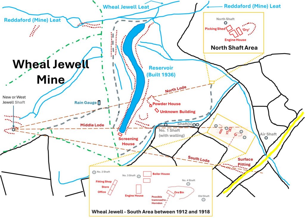
Wheal Jewell comprises a scattering of workings located on Kingsett Down and dates to the late 18th century. Today the area is dominated by a large ‘S’ shaped reservoir which was built in 1936 (around 12 years after activity at the mine ceased) to support the hydro electric scheme at Mary Tavy.
Writing in 1956, H.G Dines recorded that the mine had been abandoned initially by 1797, but reopened in 1865, then 1911 and finally 1924. Little is known of the mines’ early years in the 18th and 19th centuries but the 20th century activities have been well recorded by both Dines and Richardson and it is this period of the mines’ history which is primarily covered by this post.
In 1911, the mine was known as Wheal Jewell and Mary Tavy Mines. By 1912, the mine mine owners took the decision to suspend work on Bennett’s Lode (at Wheal Friendship) and concentrate resources at Wheal Jewell. However, the Wheal Friendship dumps were still being worked over for tin, arsenic and tungsten (scheelite) at this time. Wheal Jewell is situated on the western edge of the Dartmoor granite, which is mainly metamorphosed shales and grits of Culm Measures age with intruded greenstones, enabling the mining of tin, arsenic and mispickel. The mine comprised three lodes named; north, middle and south. Records indicated that Wheal Jewell and Mary Tavy Mines, between 1913 and 1924, produced 1,367 tons of arsenic and 288 tons of mispickel between the two locations.
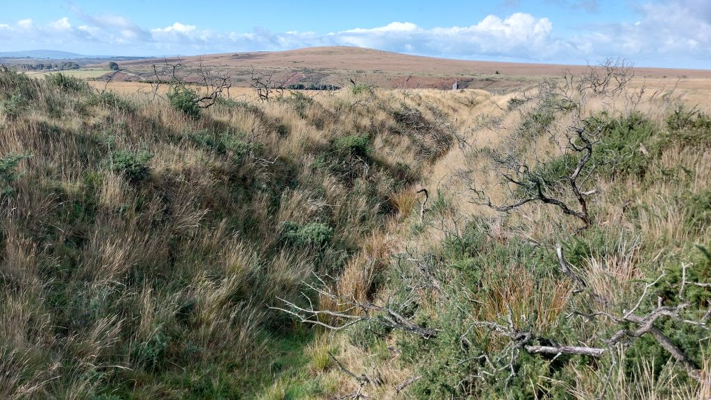
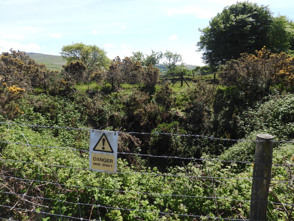
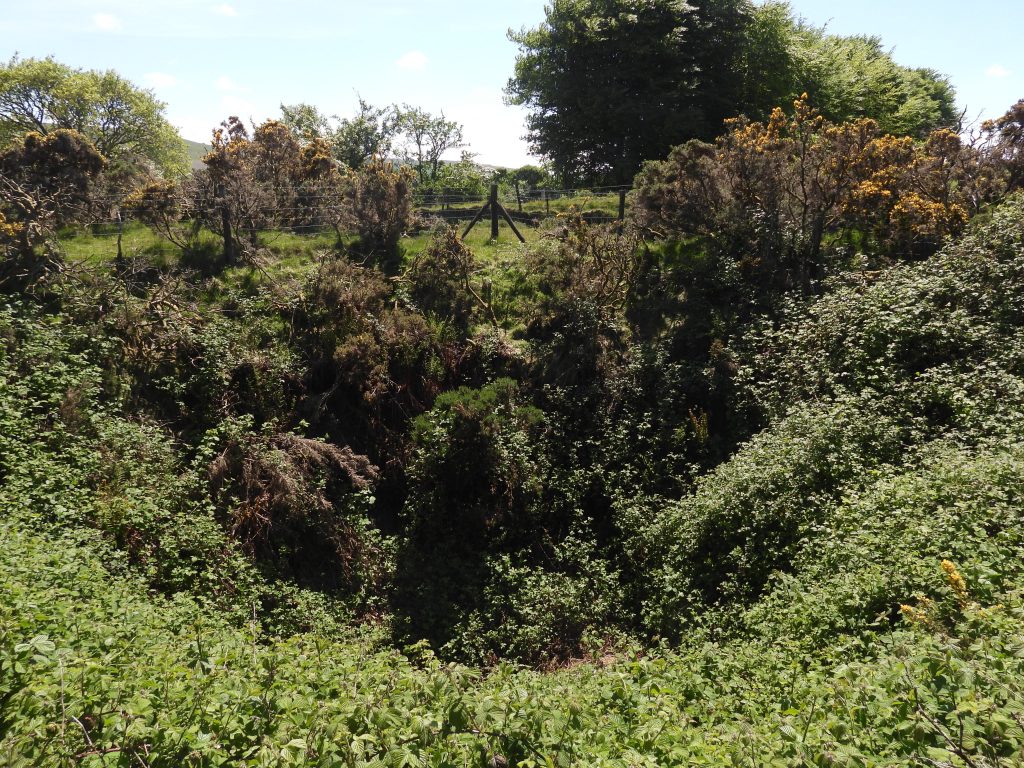
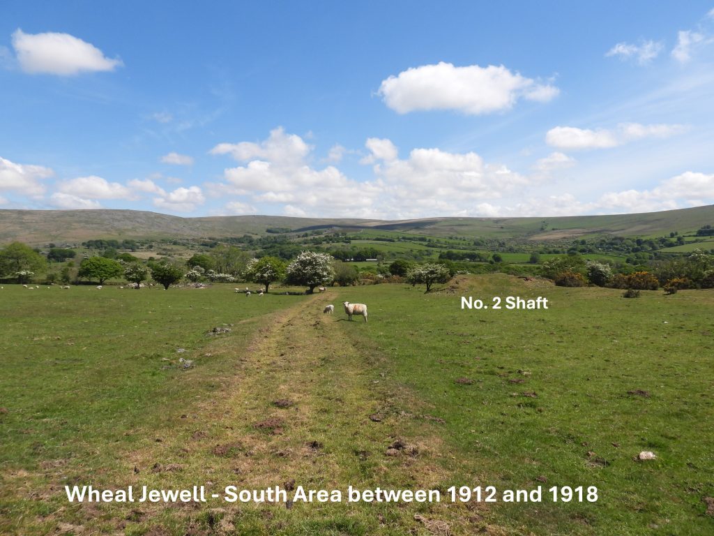
Richardson records there was at least six shafts between the Willsworthy / Horndon Road and the present day reservoir. That said, only two of these shafts were known to have been worked to any significant extent in the 1912-18 period; No 3 shaft in the ‘south area’ and the ‘north shaft’. There is a shaft known as West Jewell or New Shaft to the west of the reservoir which is thought wasn’t worked in the 20th century. Interestingly, Dines recorded that North Lode and South Lode each converged westward towards Middle Lode and the three were thought to have intersected in the neighbourhood of West Jewell Shaft, which is shown on the annotated sketch map in this post.
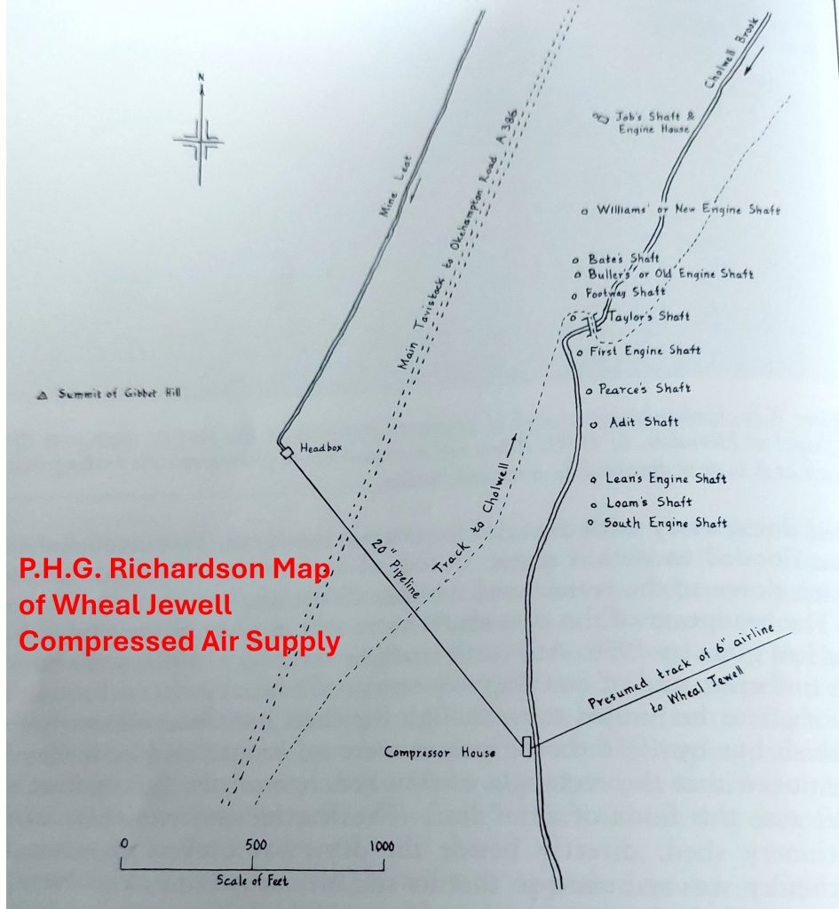
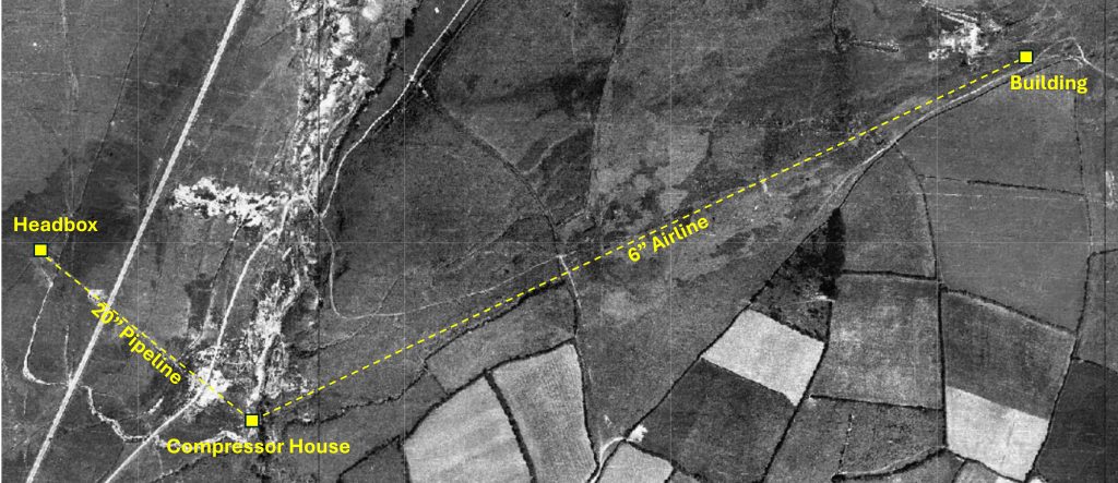
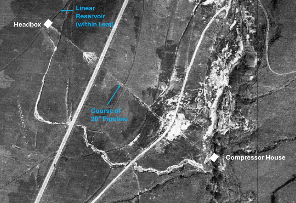
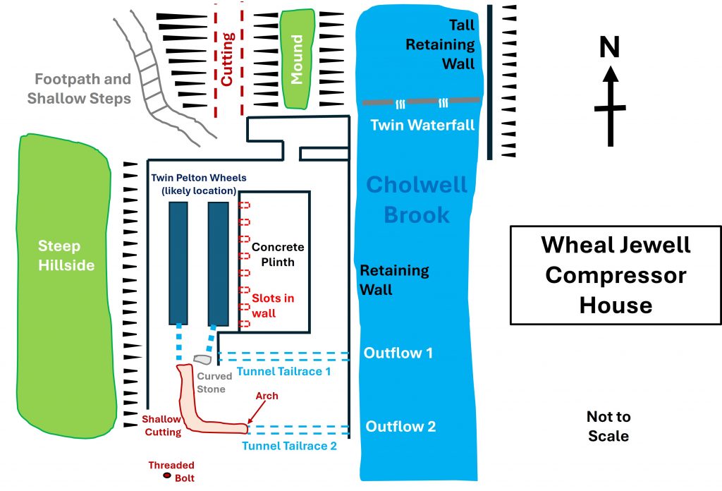
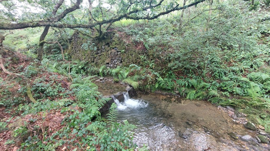
Of particular interest in the 20th century operation, was the source of power for the mine which was provided by a two-stage air compressor. Water was supplied by the extended Reddaford (Mine) Leat onto the slopes of Gibbet Hill, where it was fed via a 20″ pipe down hill (across the modern A386) to a Compressor House next to the Cholwell Brook. At the Compressor House, there where two Pelton Wheels which were used to convert the water power into compressed air which was then fed to the mine via a 6″ cast iron main.
Bibliography
P.H.G Richardson (1992) – Mines of Dartmoor and the Tamar Valley after 1913 (pages 47-50)
H.G Dines (1956) – The metalliferous mining region of south-west England (pages 804, 807 and 810)
Stephen Holley (2025) – Pers. Conv
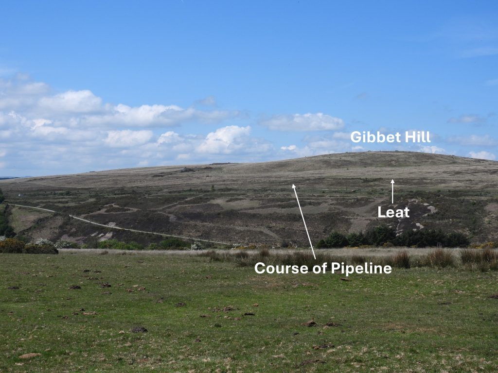
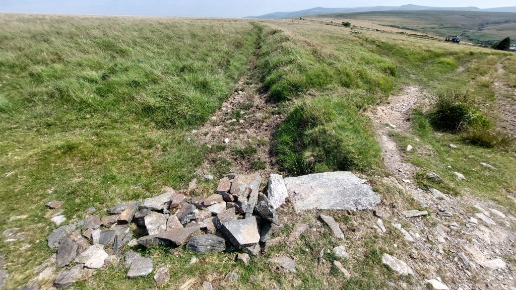
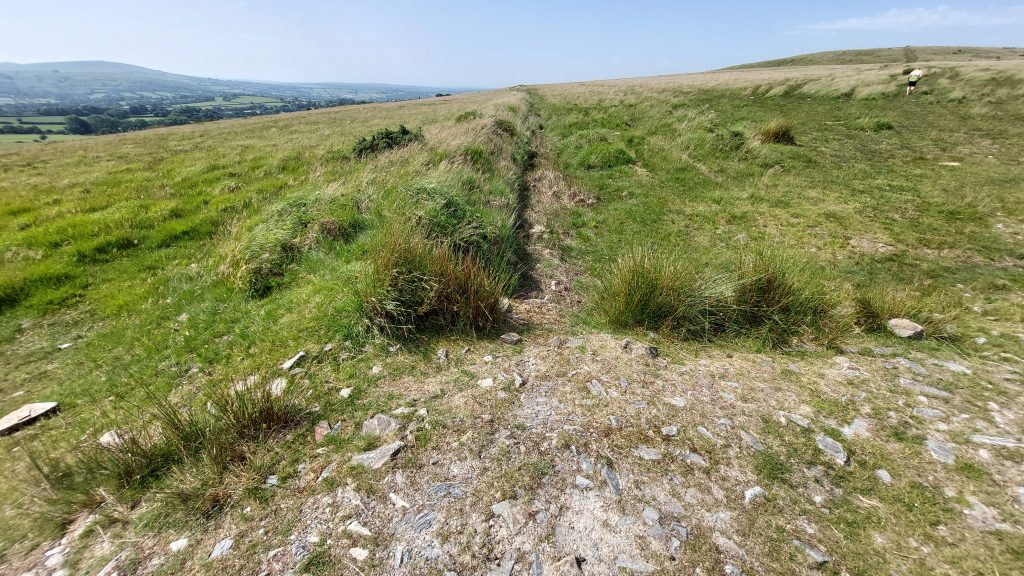
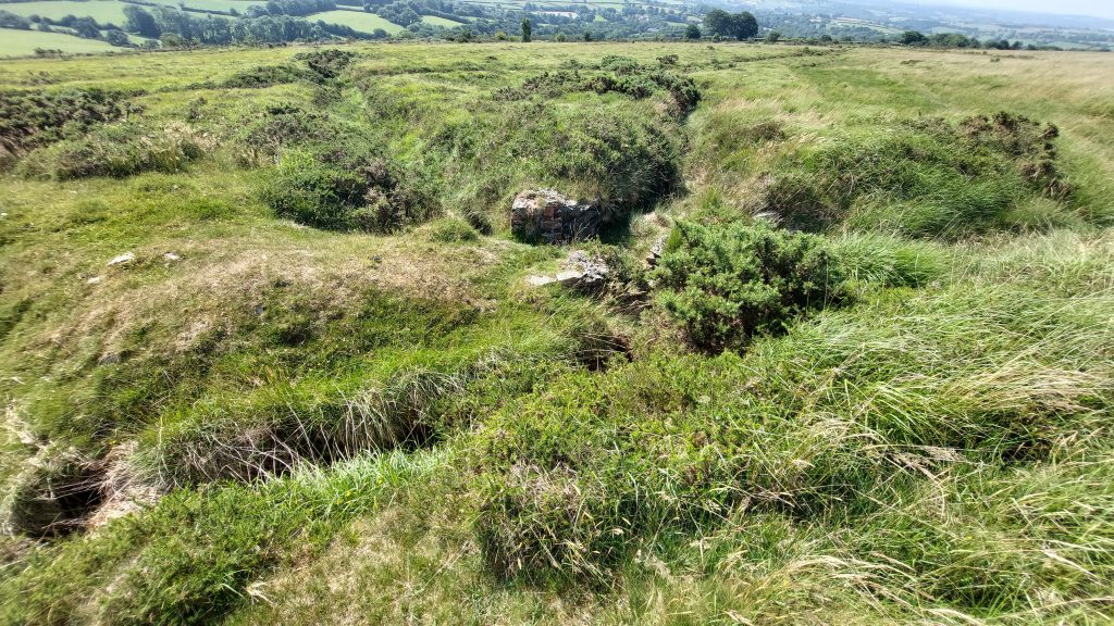
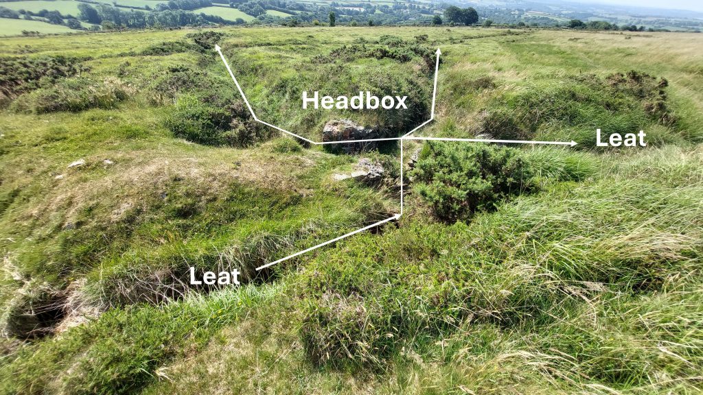
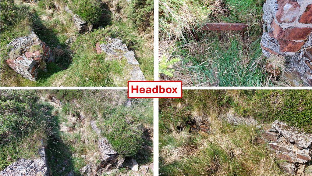
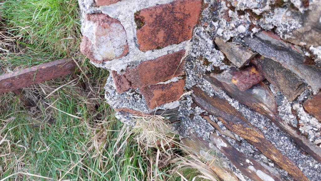
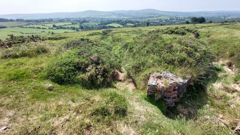
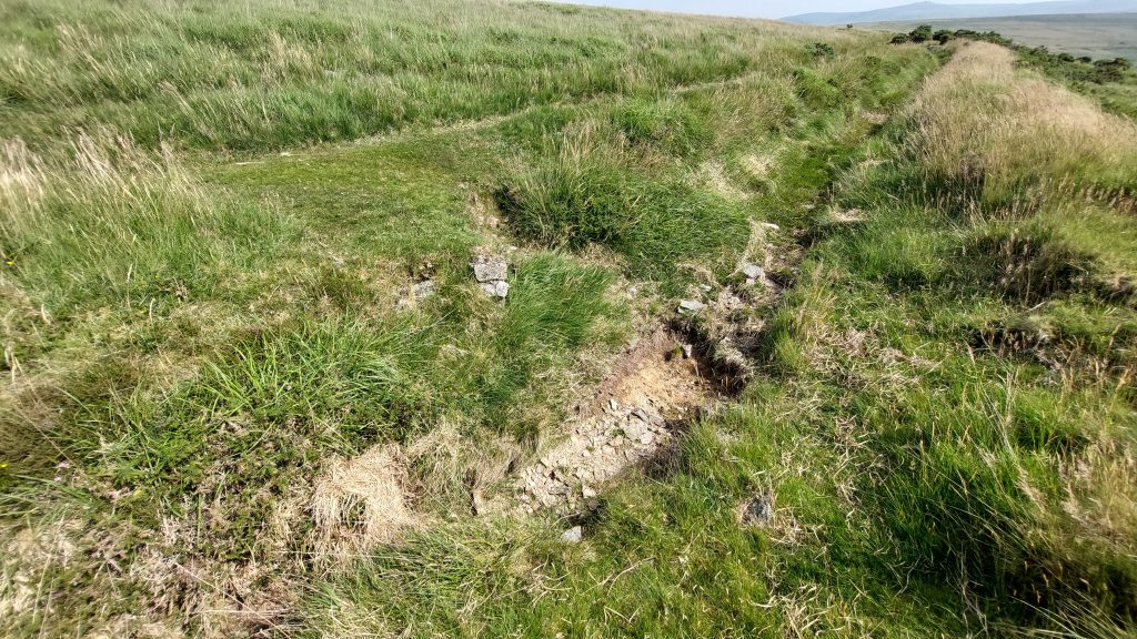
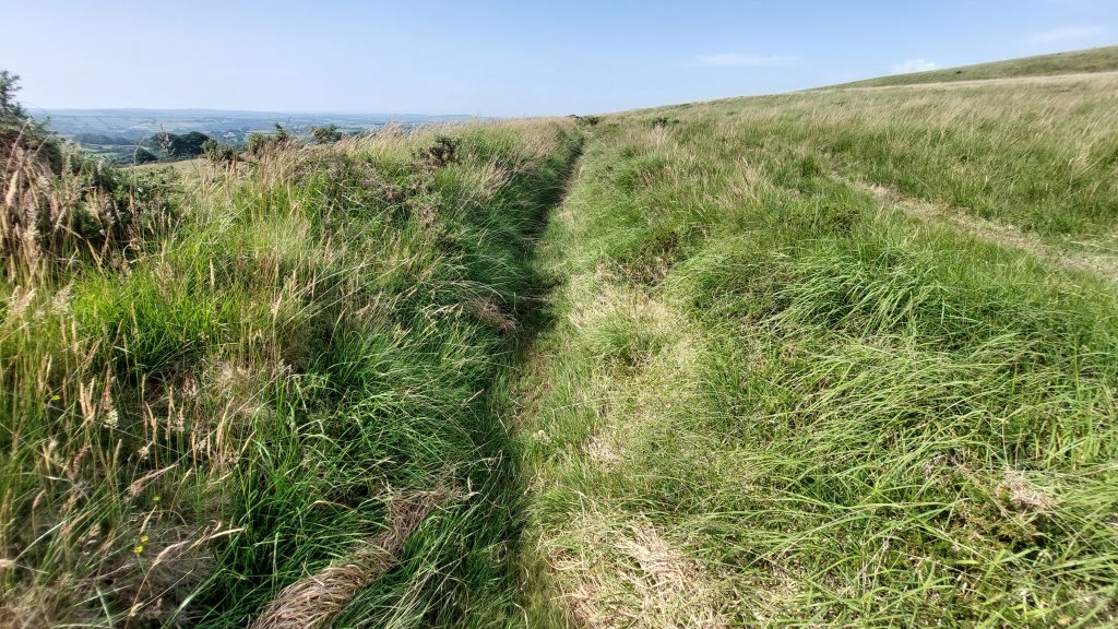
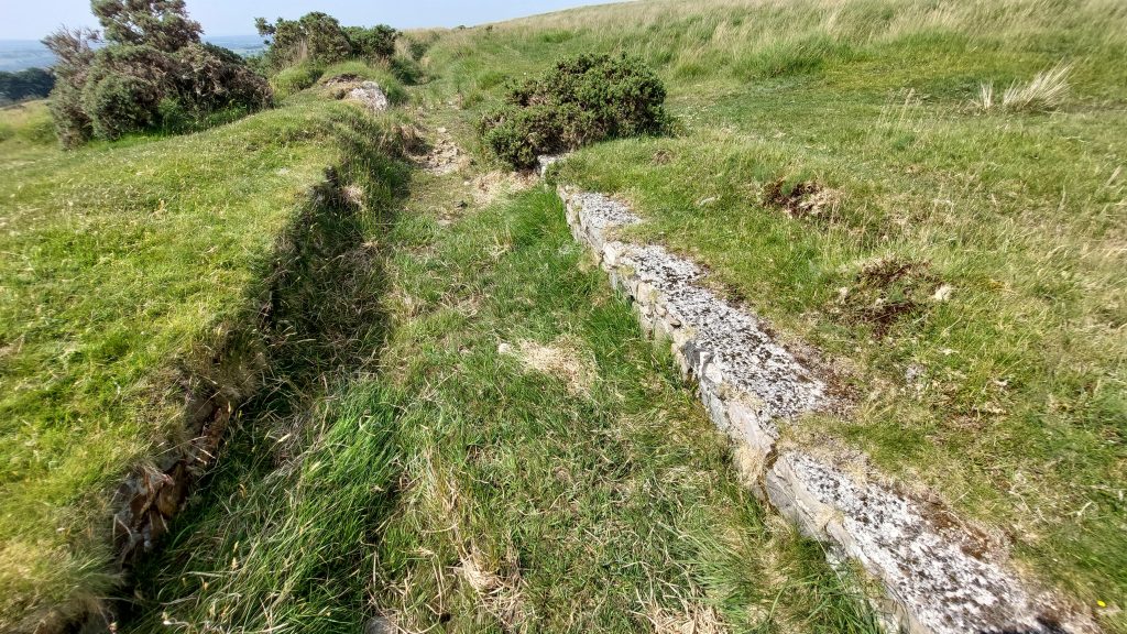
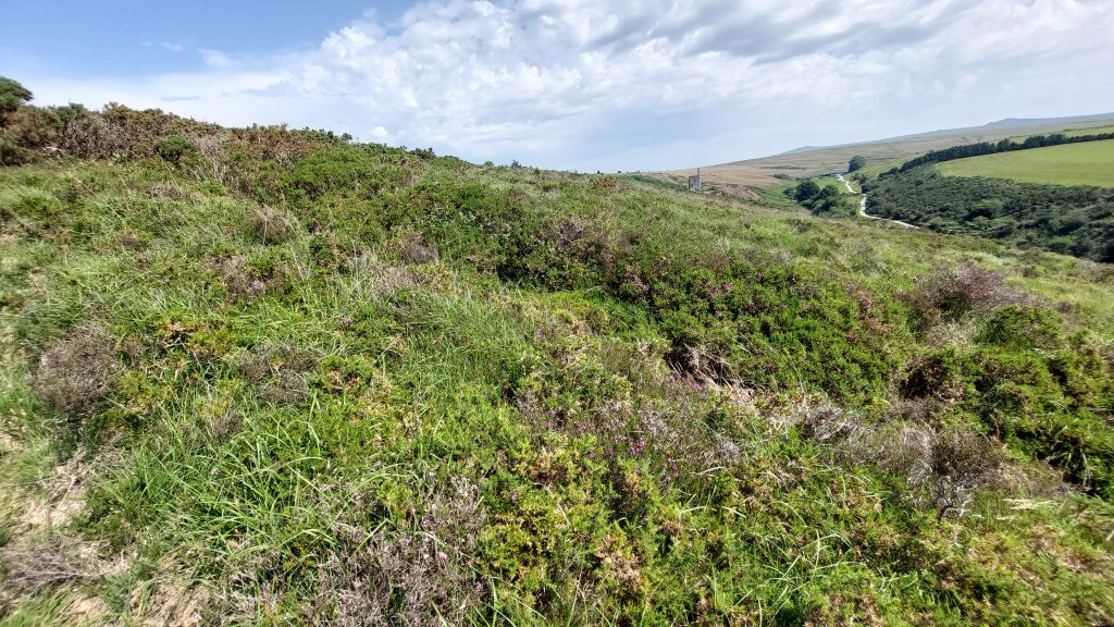
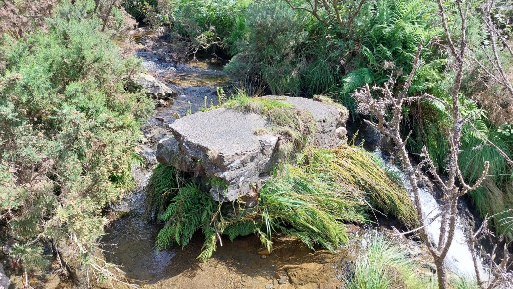
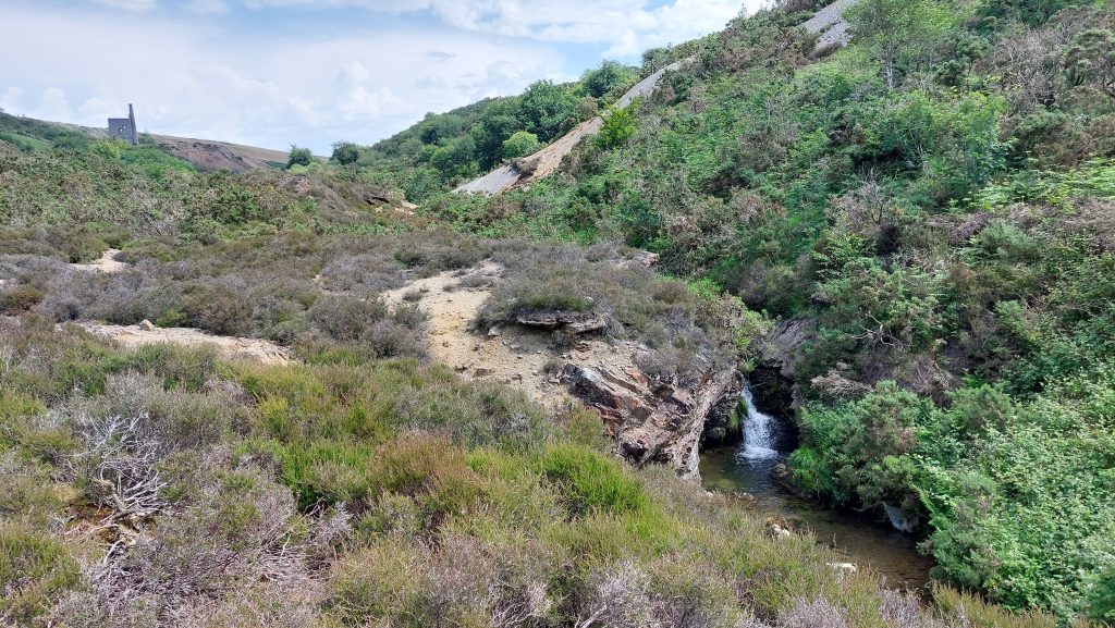
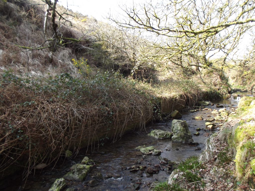
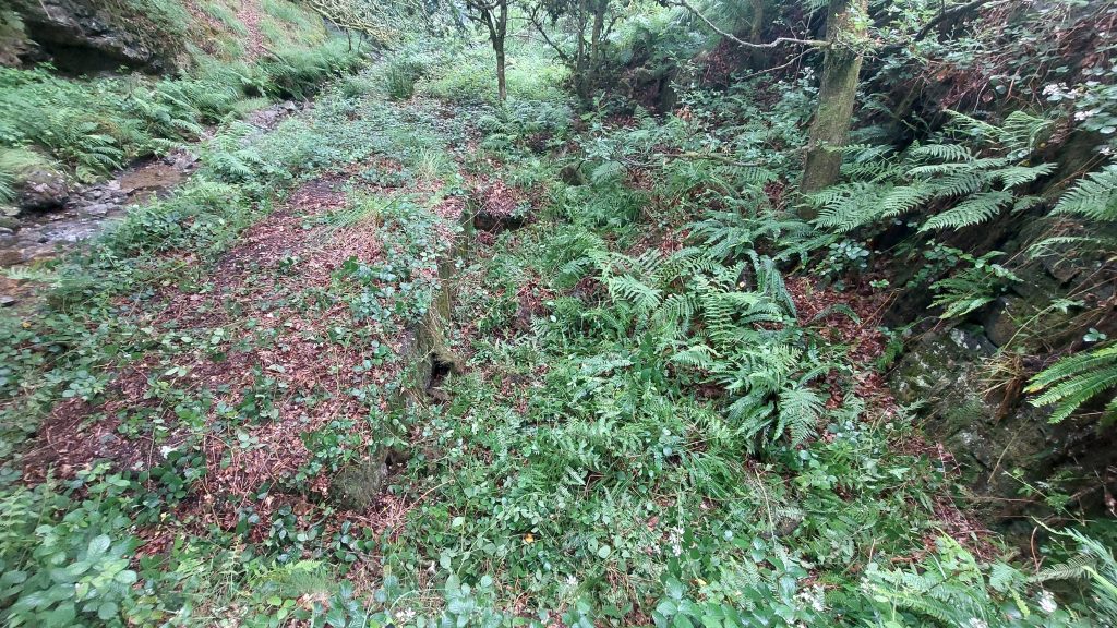
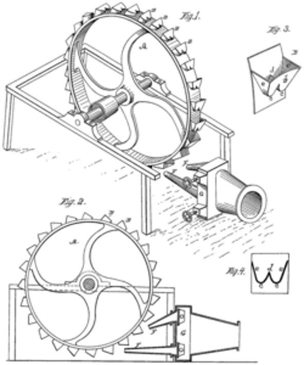
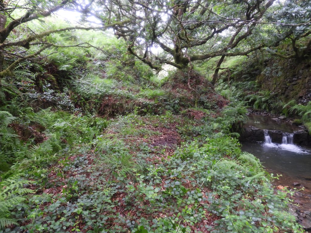
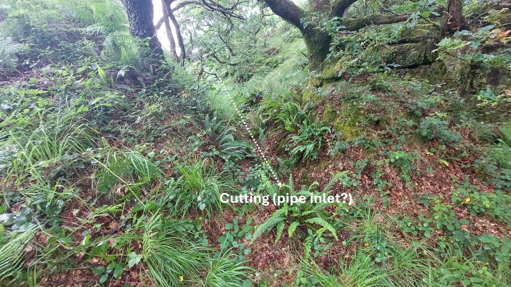
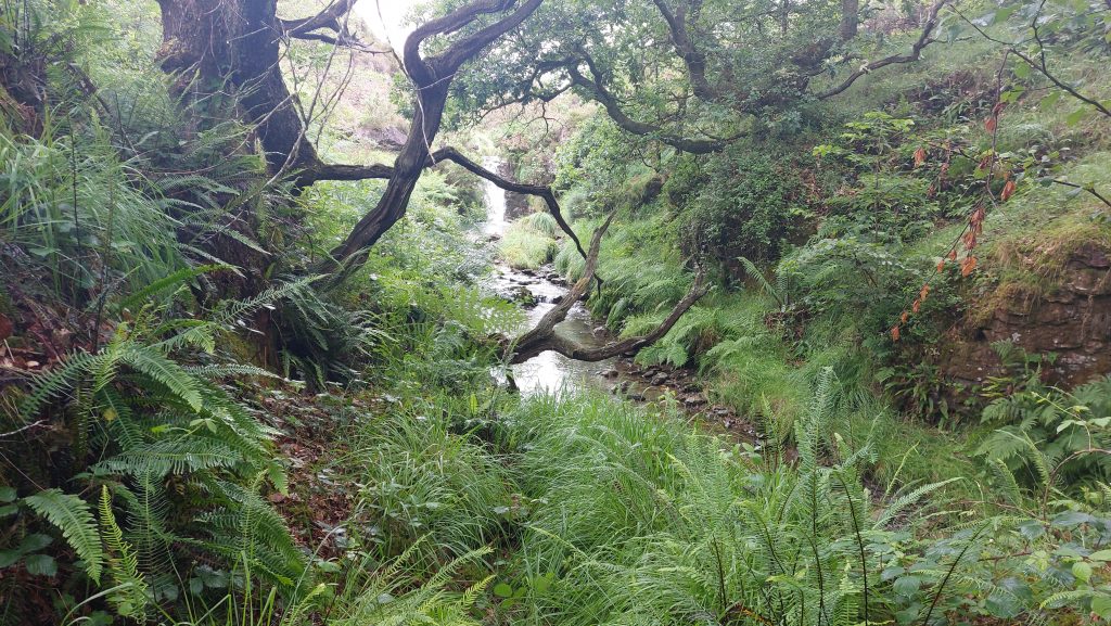
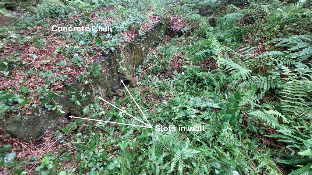
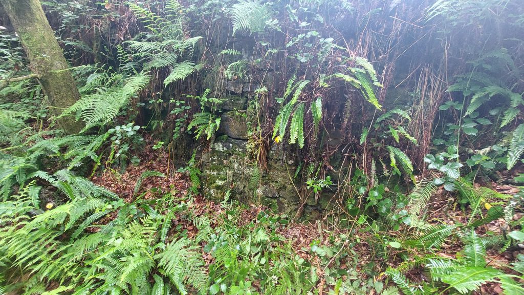
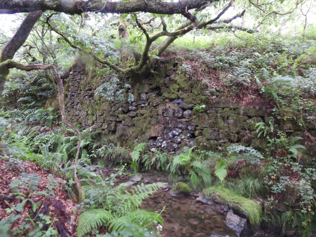
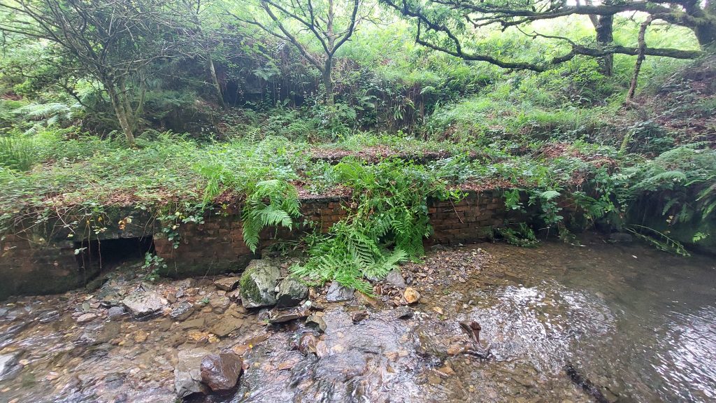
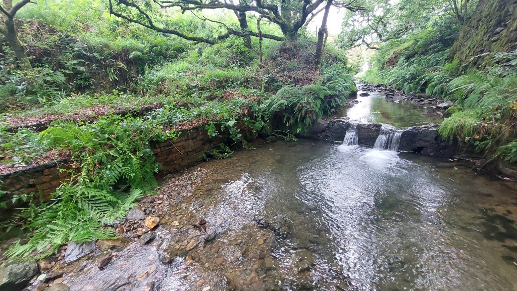
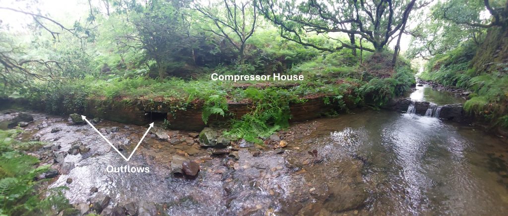
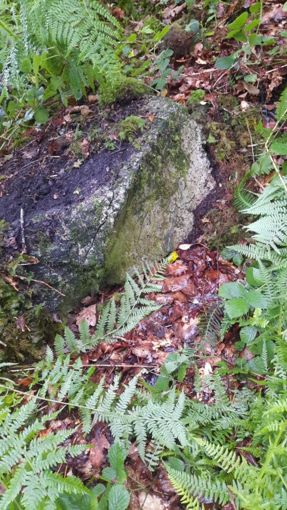
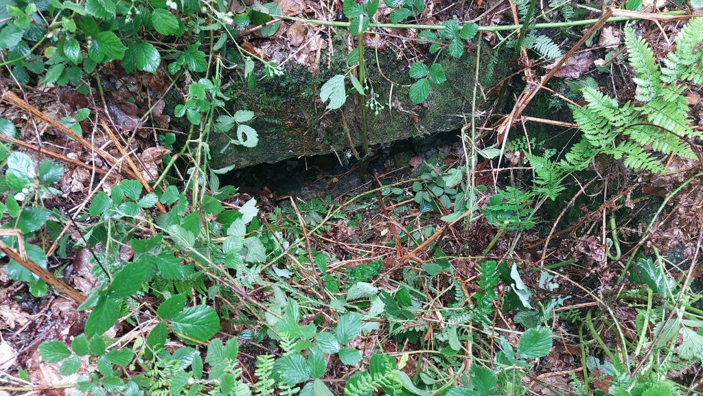
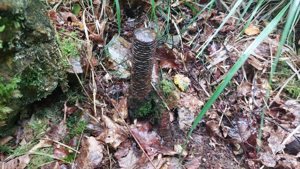
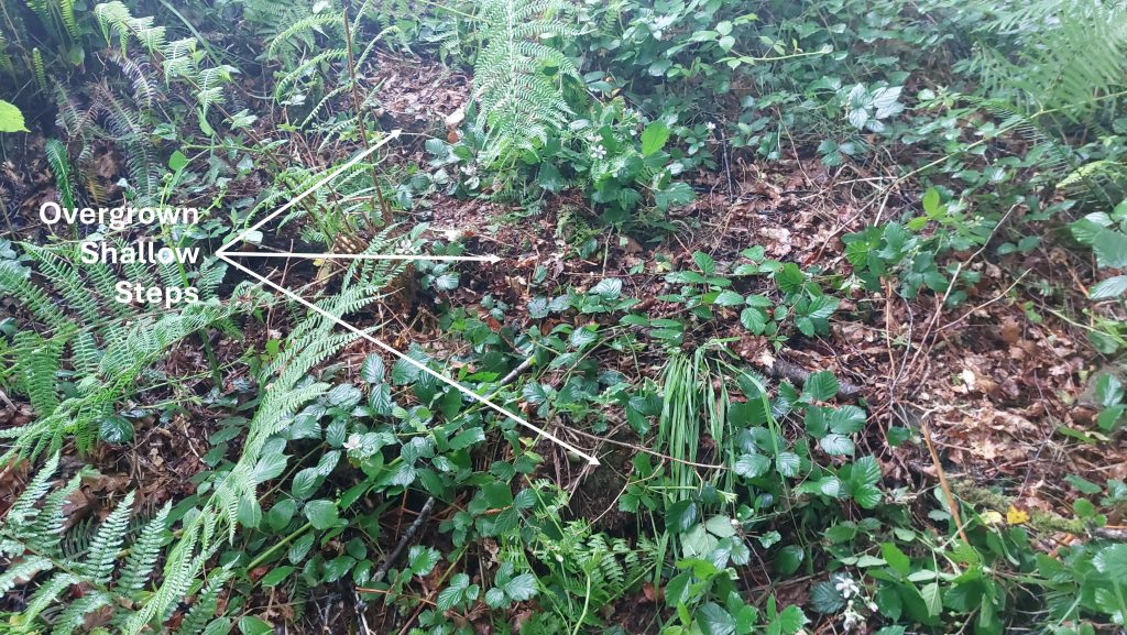
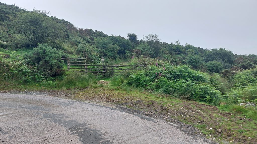
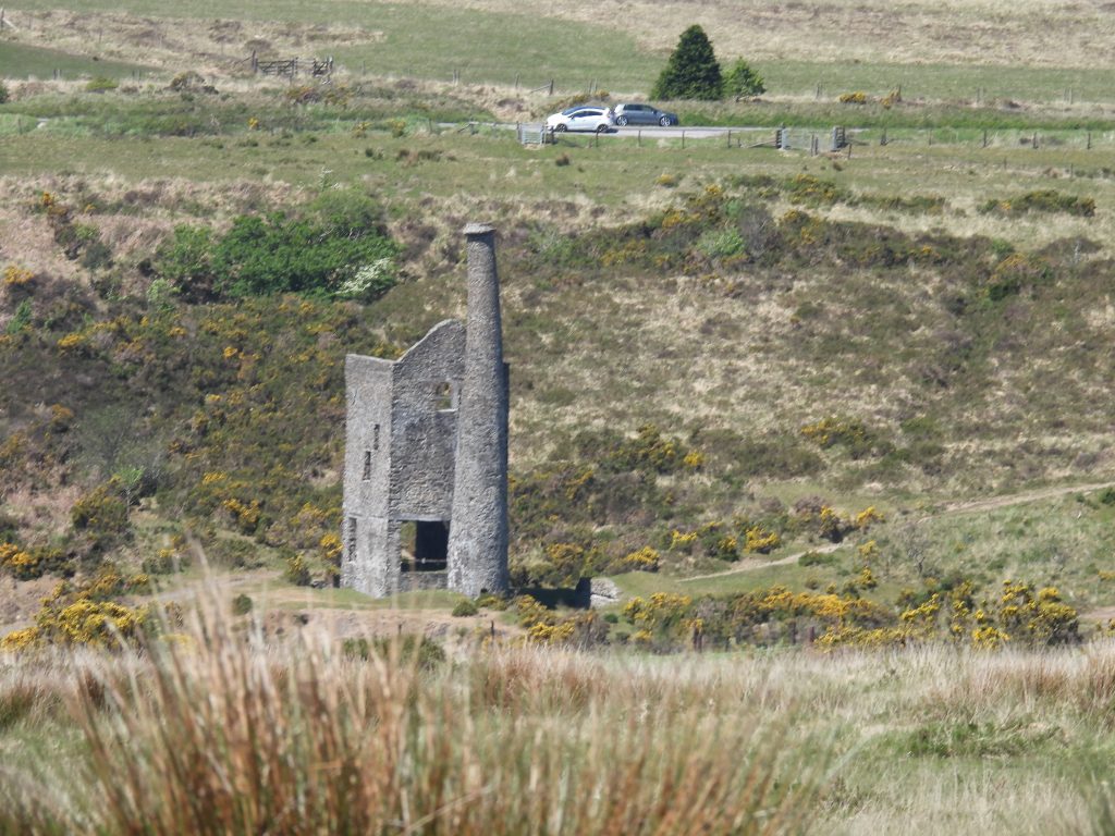
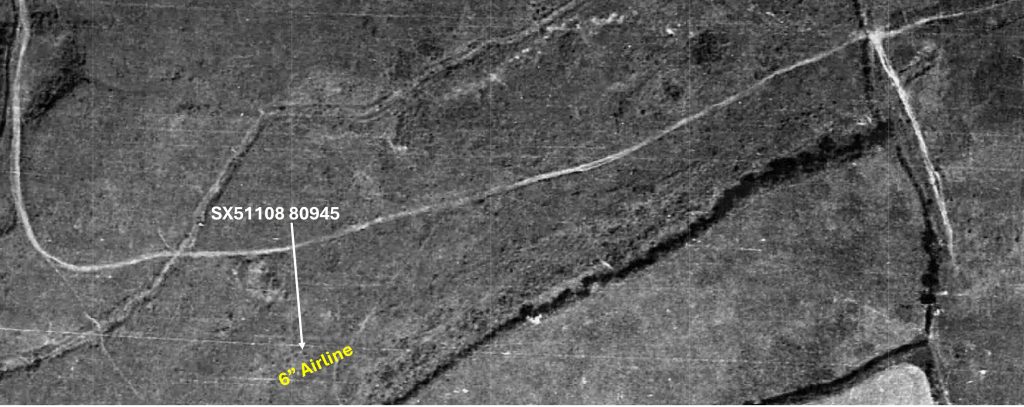
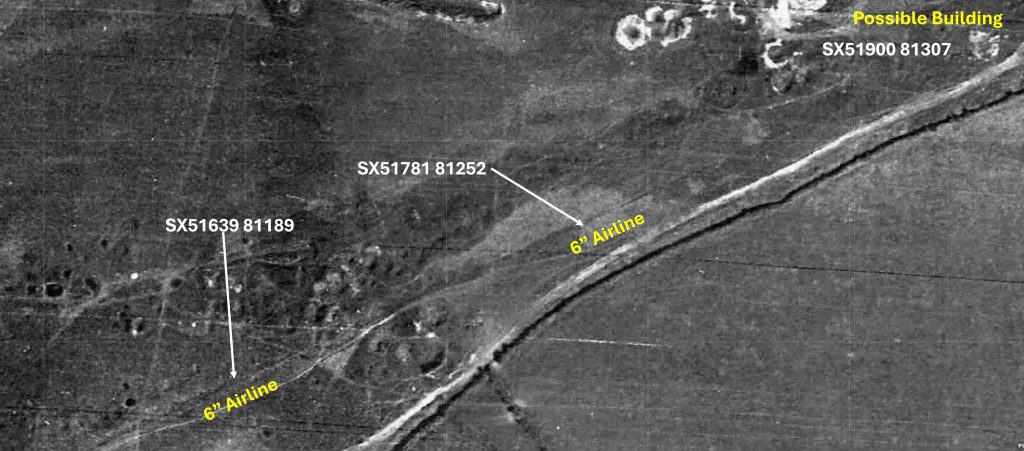
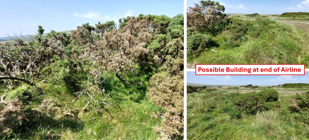
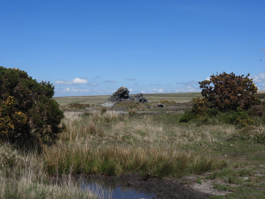
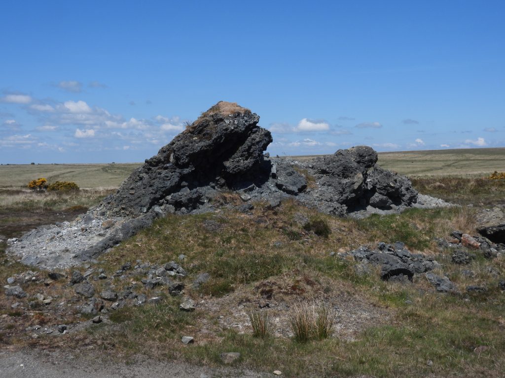
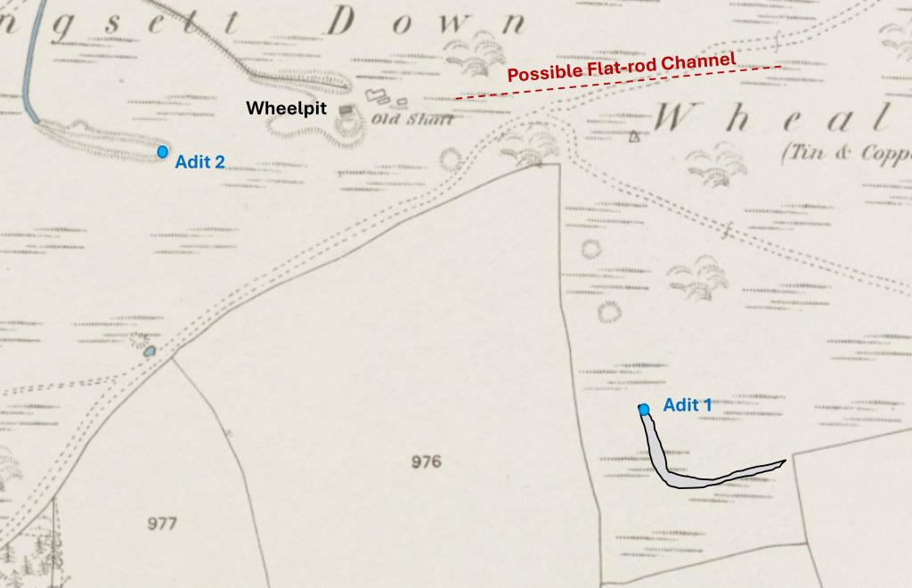
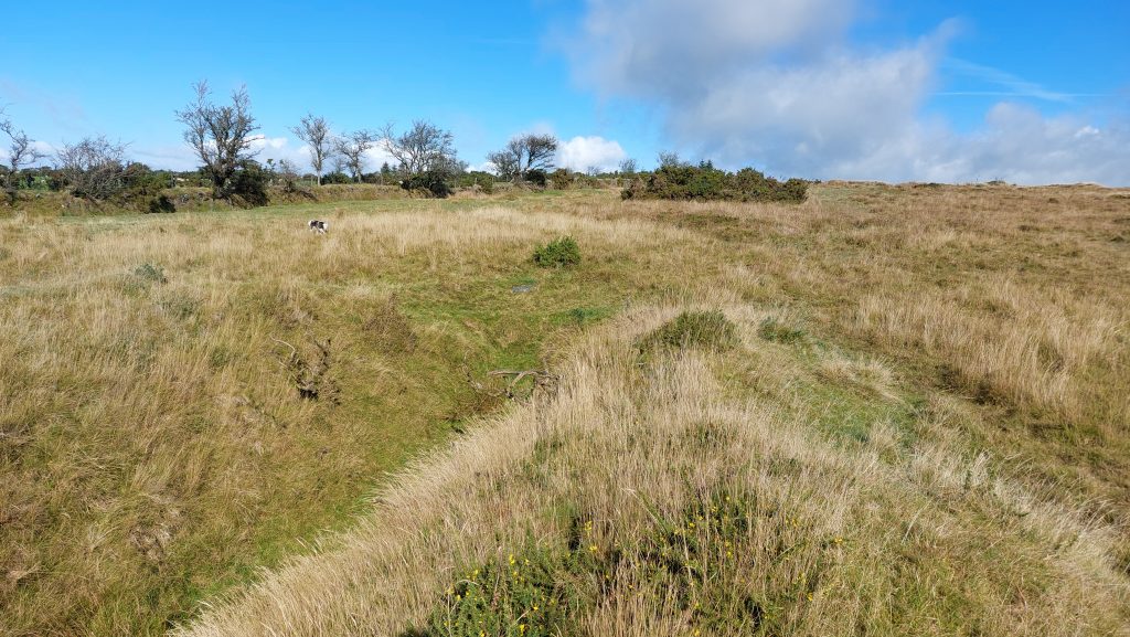
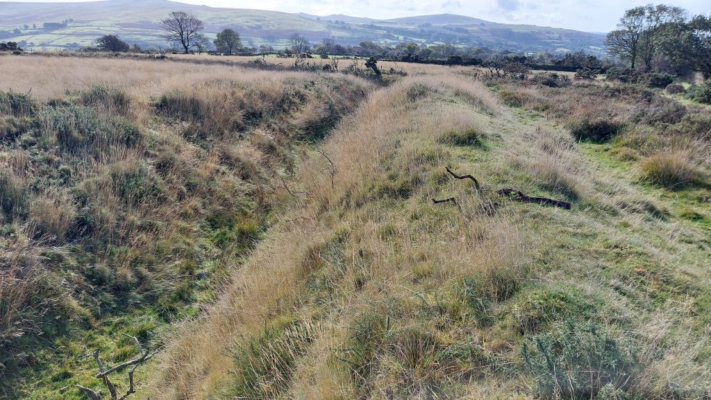
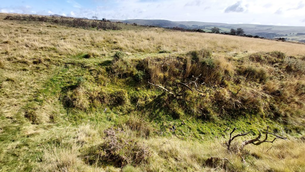
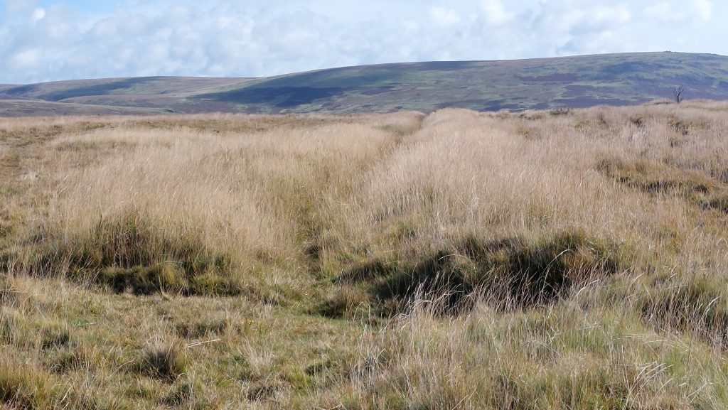
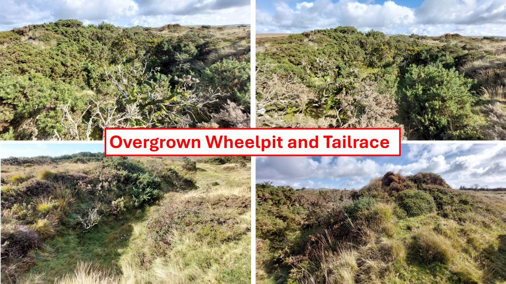
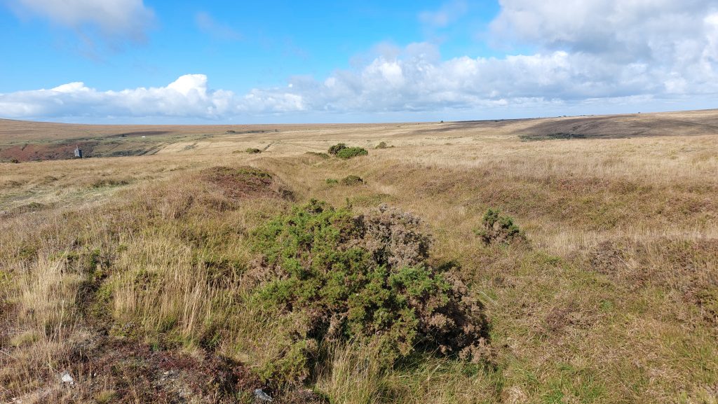
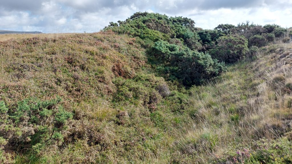
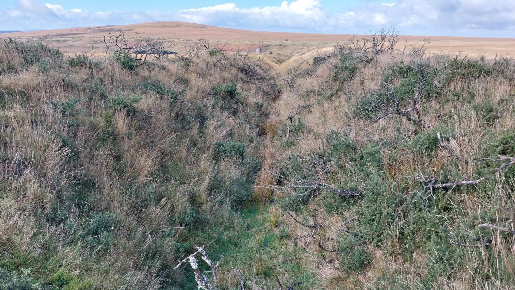
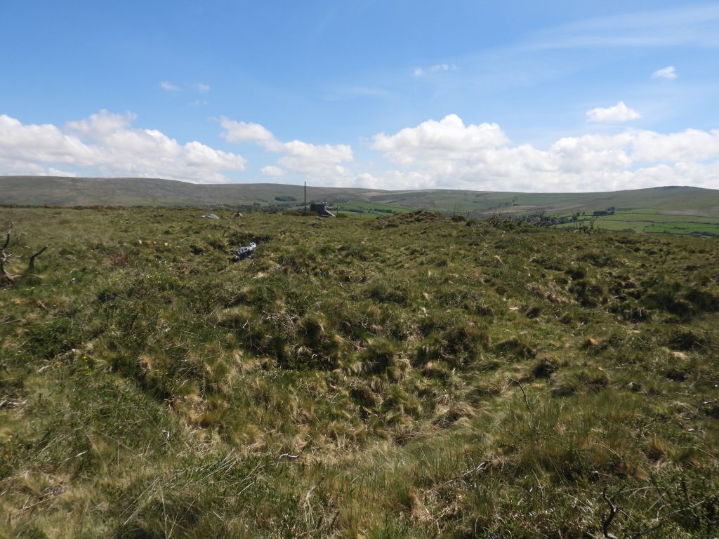
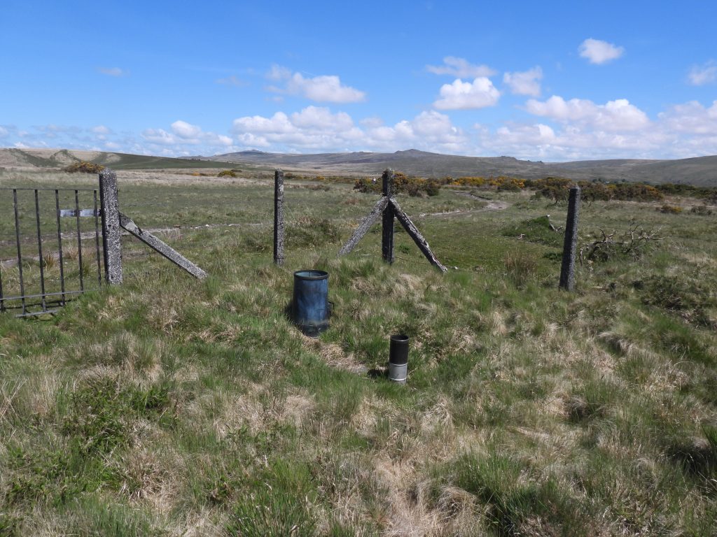
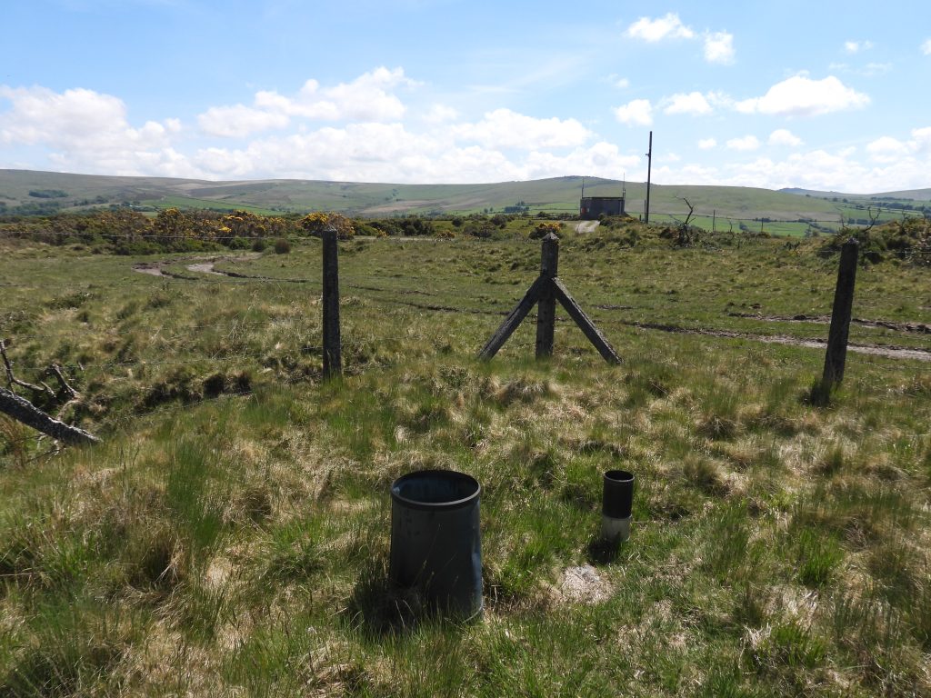
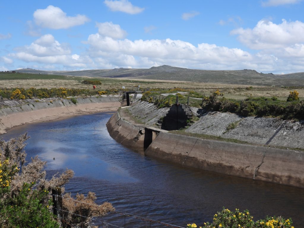
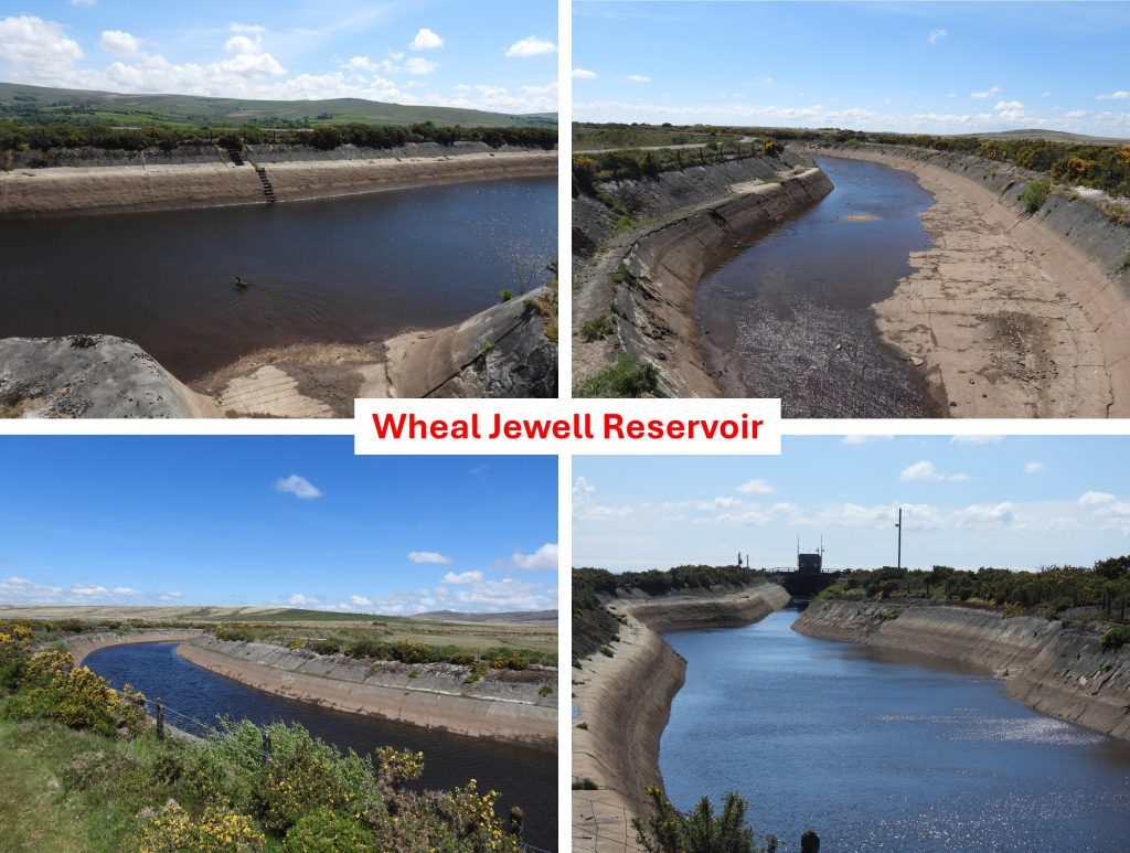
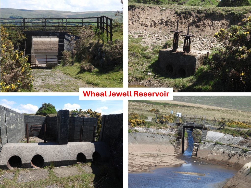
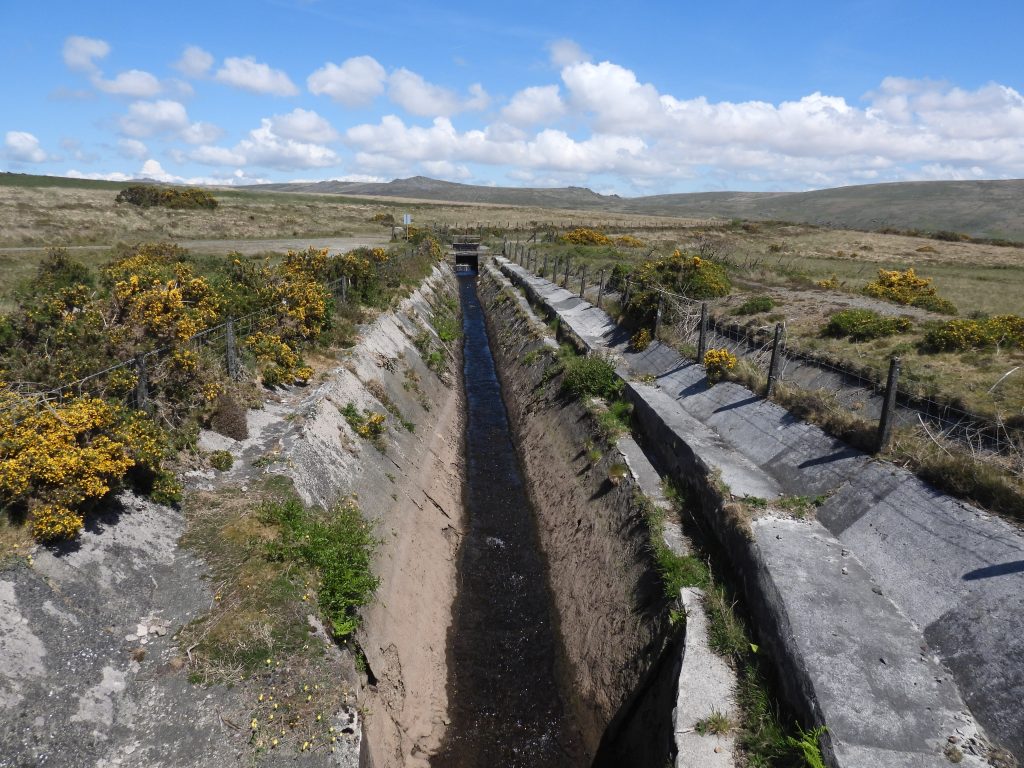
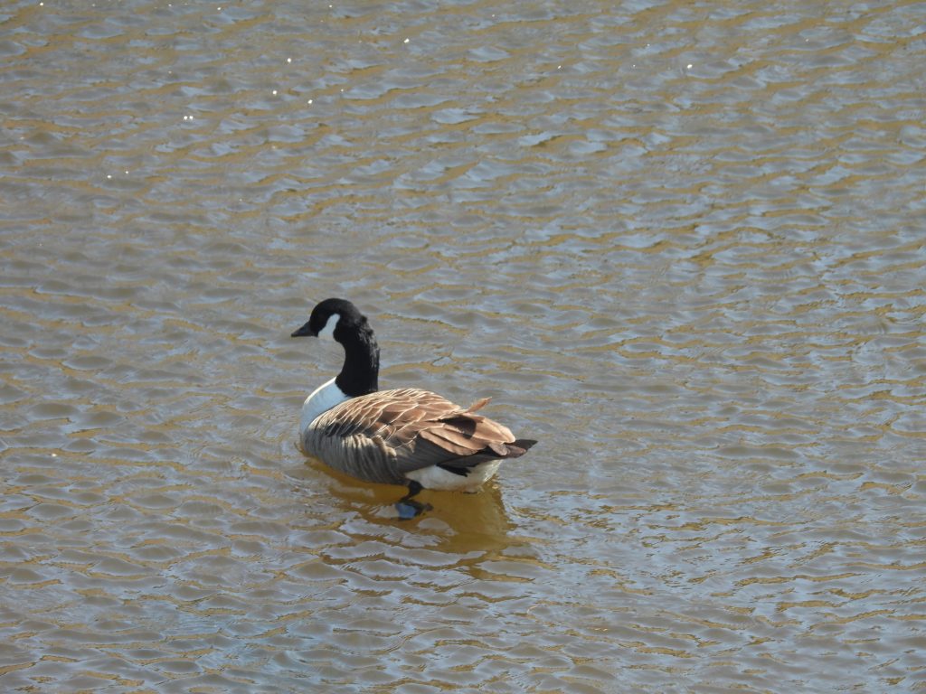
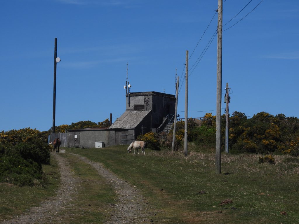
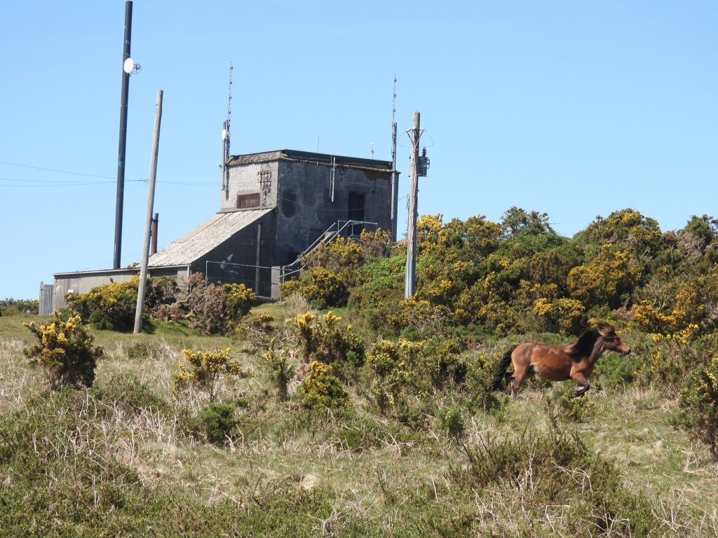
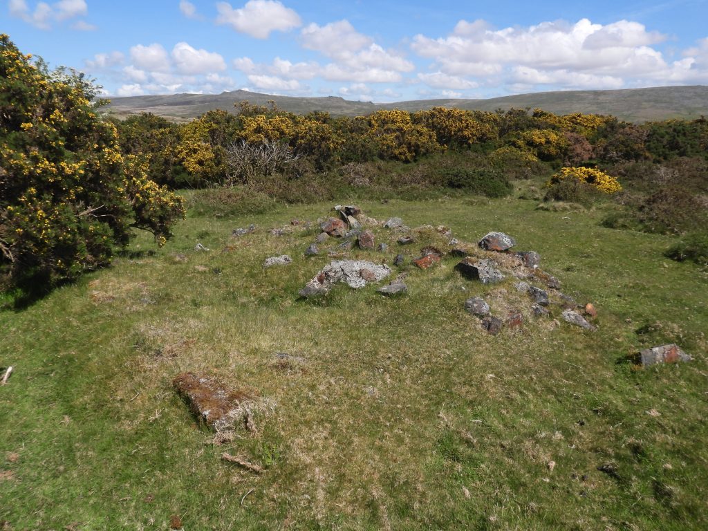
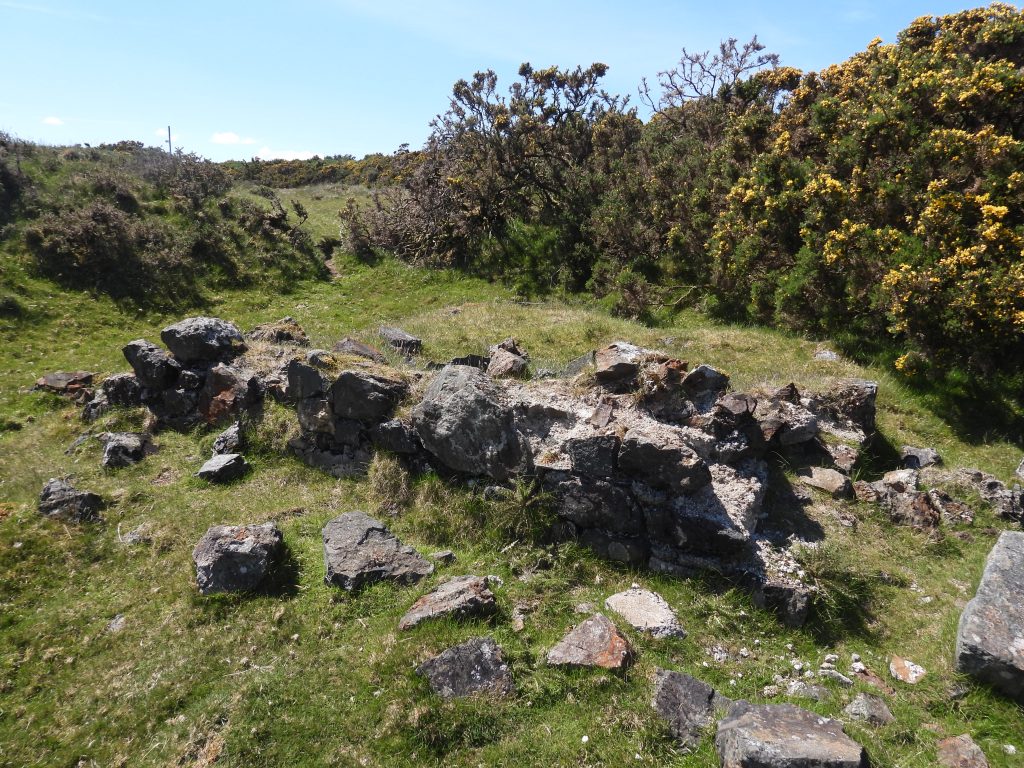
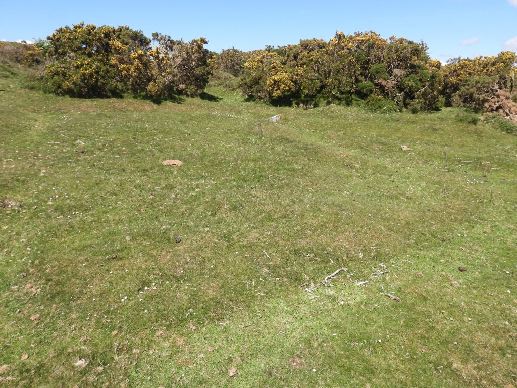
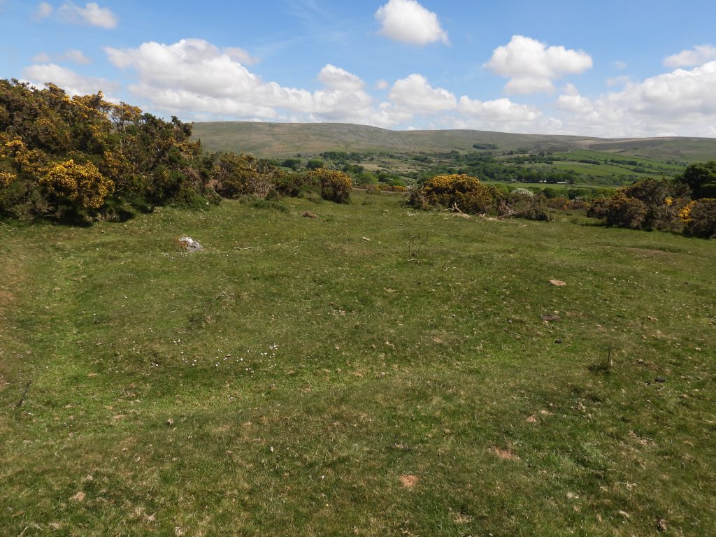
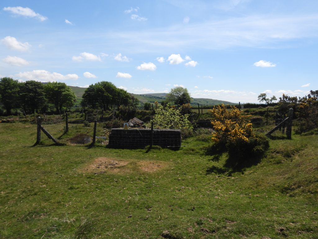
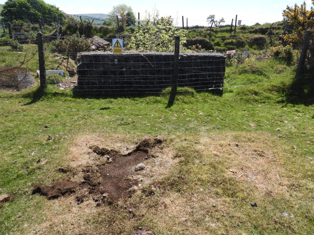
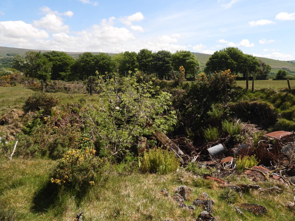
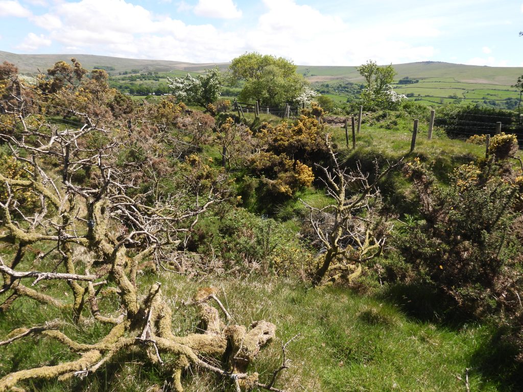
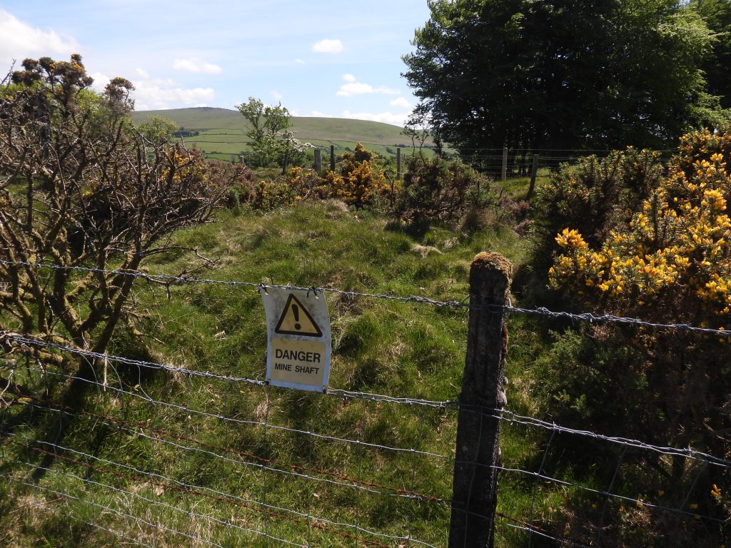
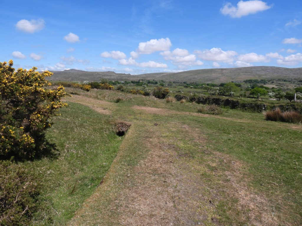
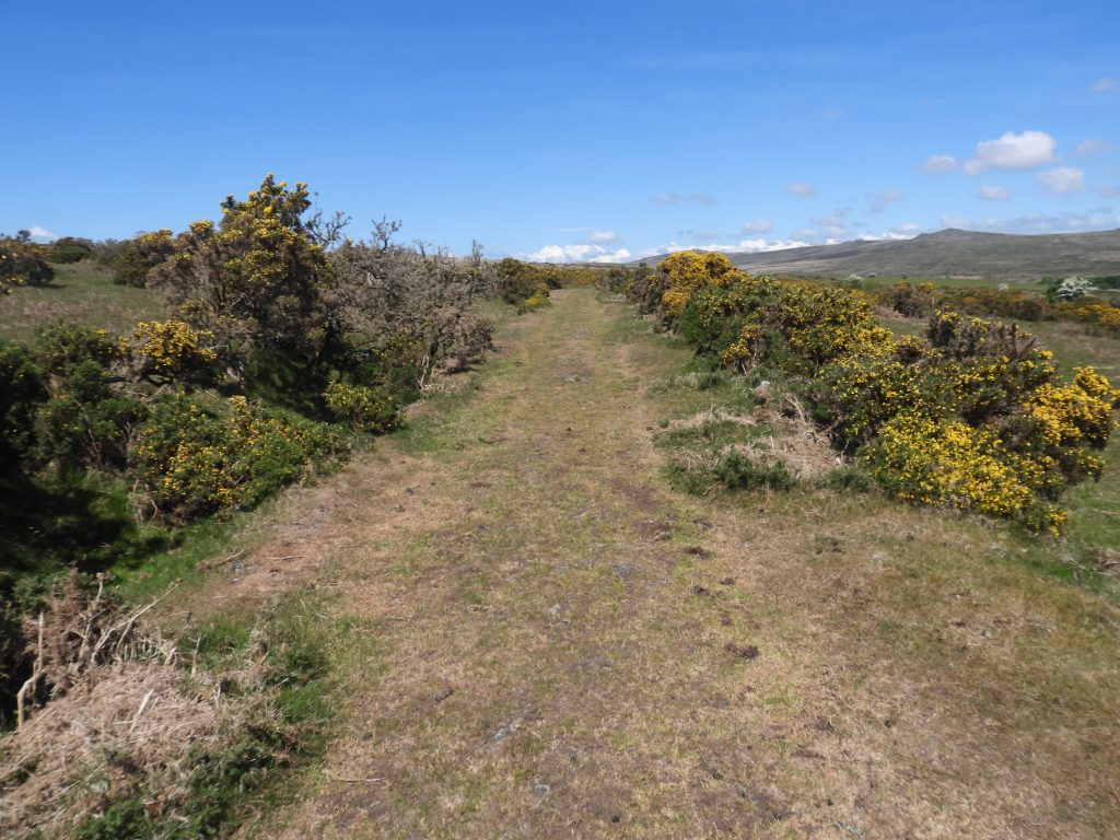
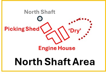
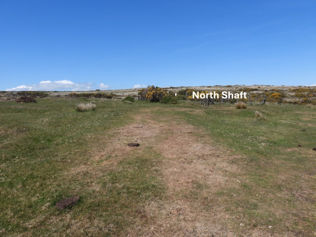
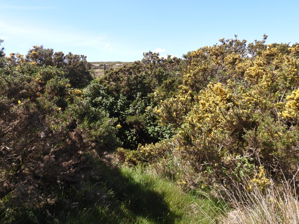
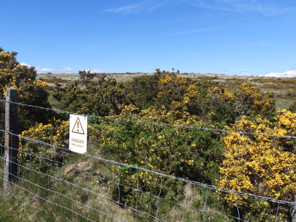
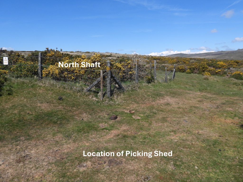
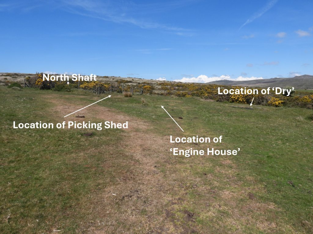
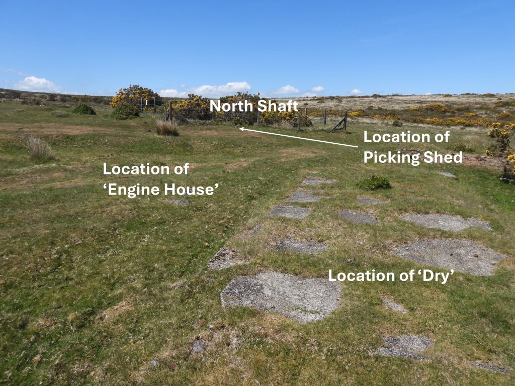
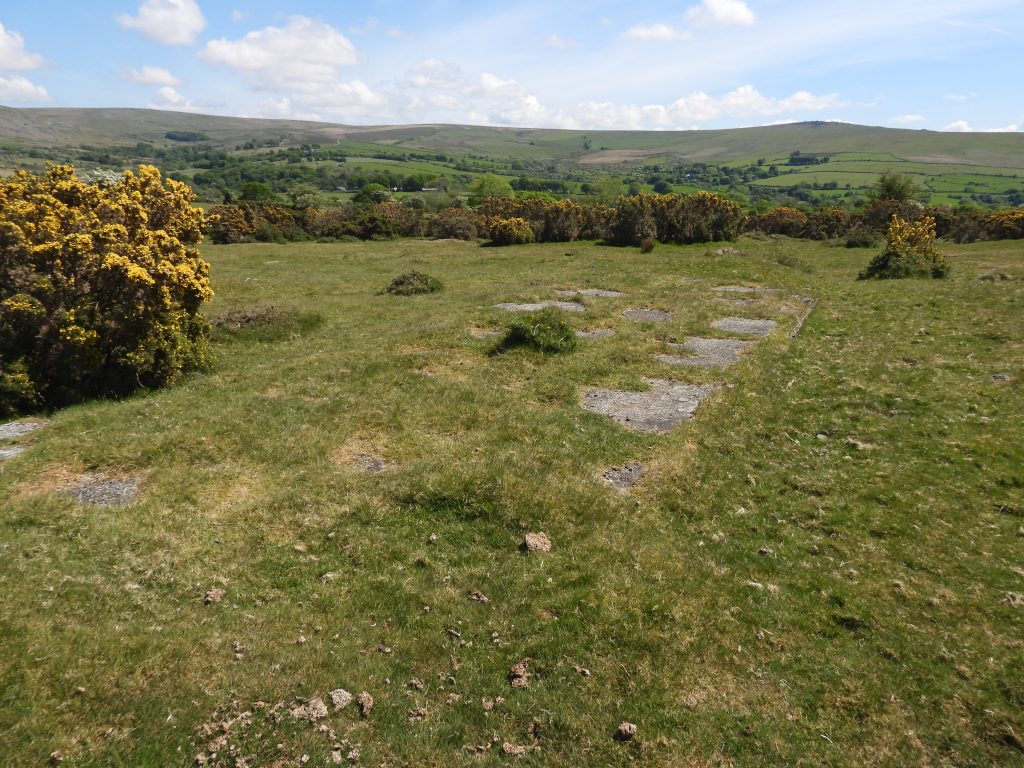
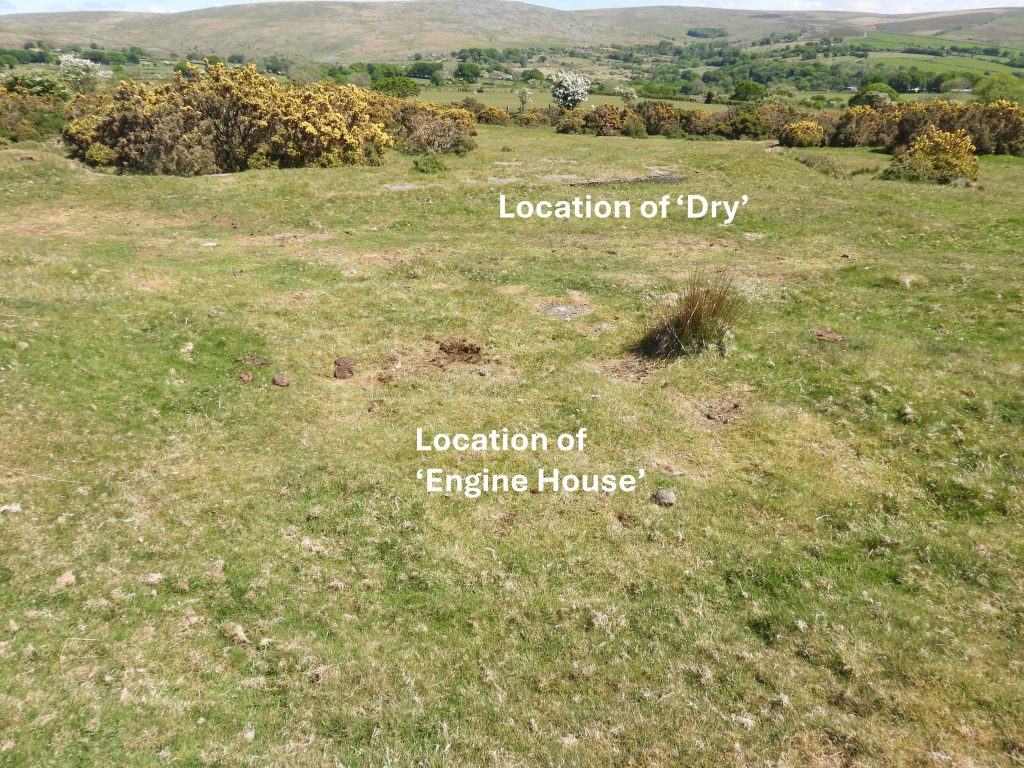
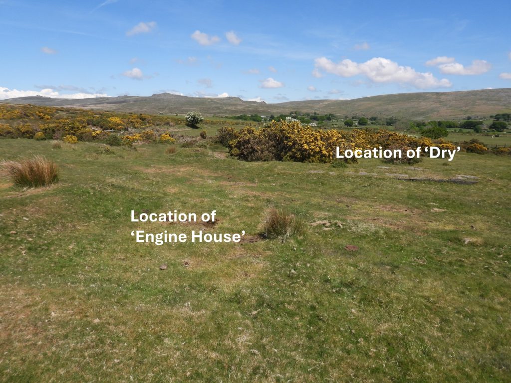
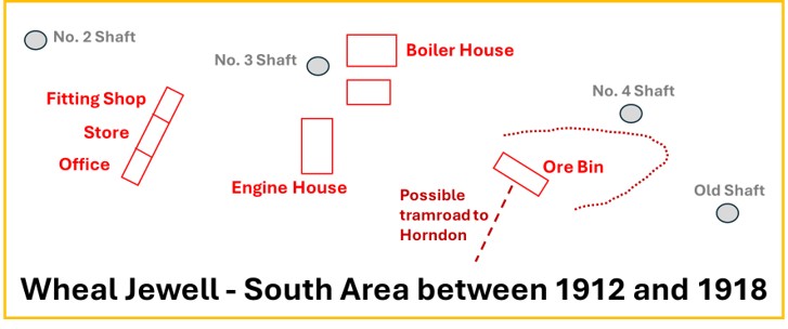
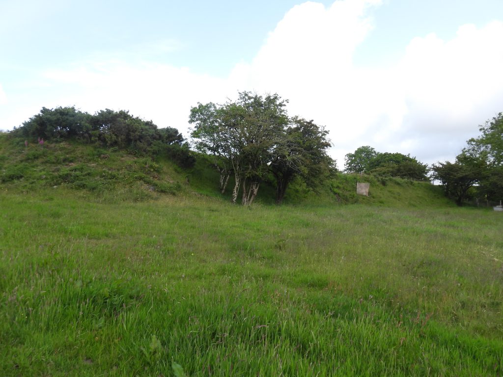
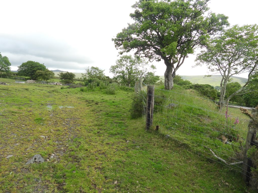
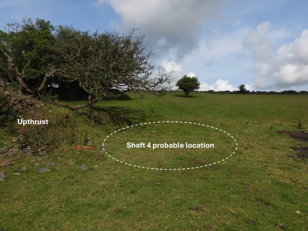
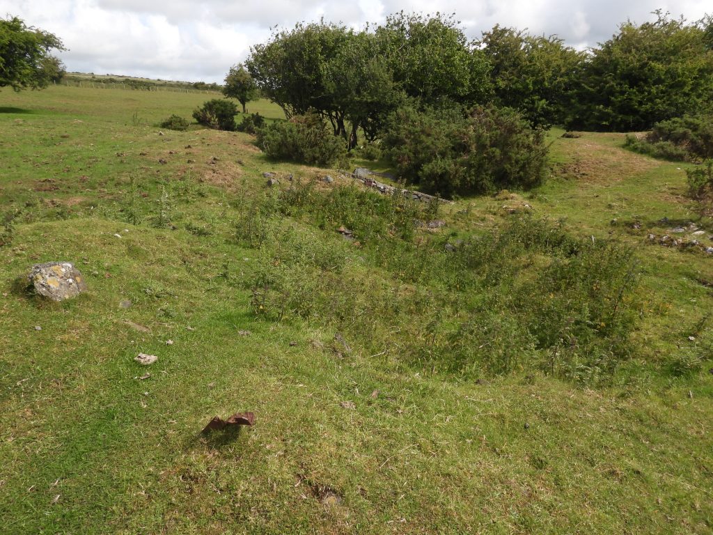
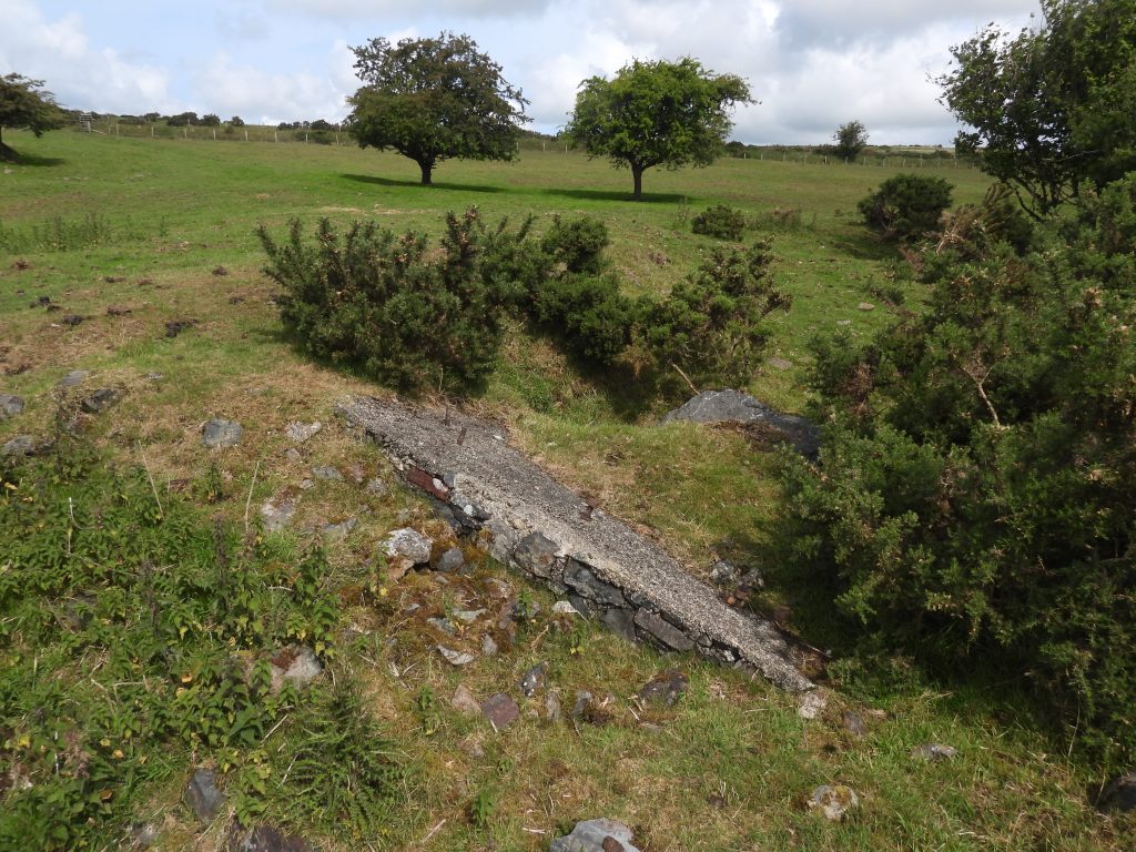
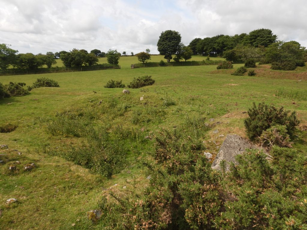
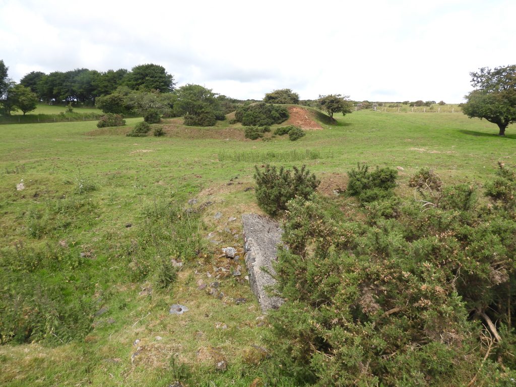
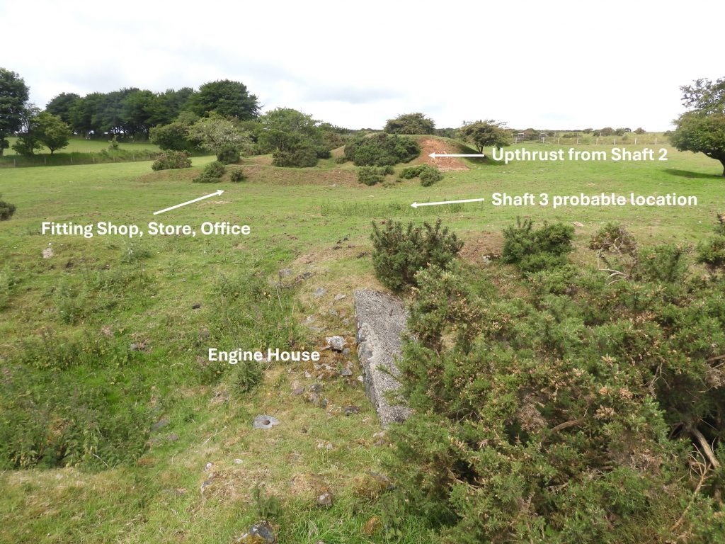
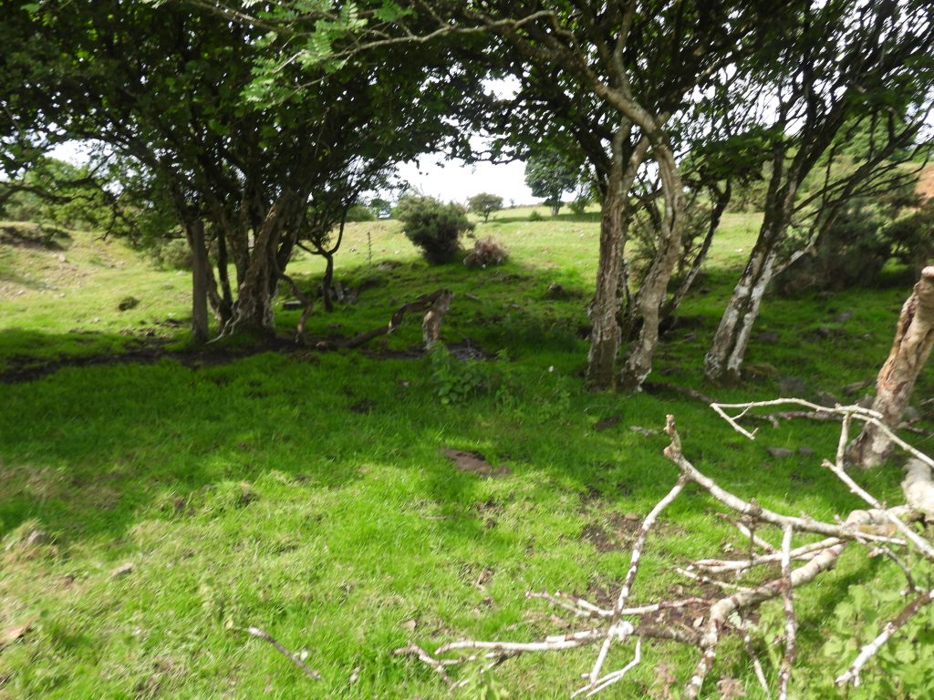
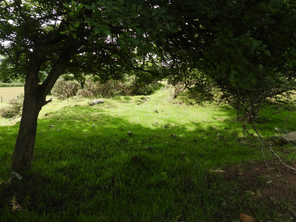
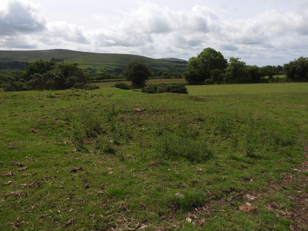
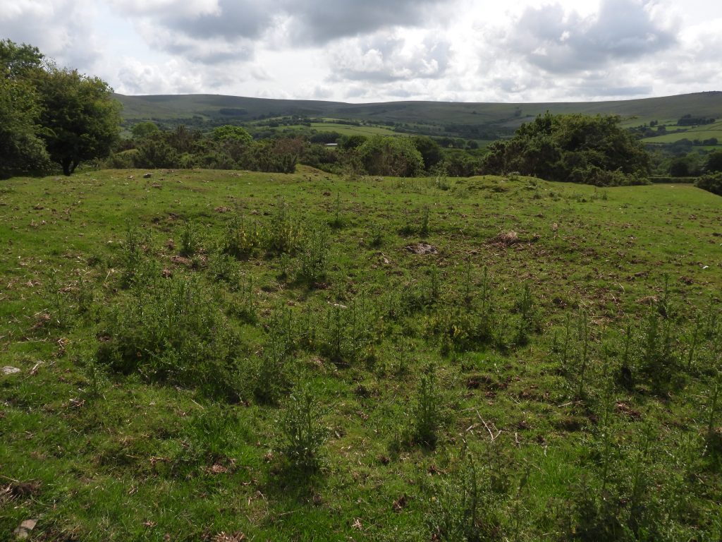
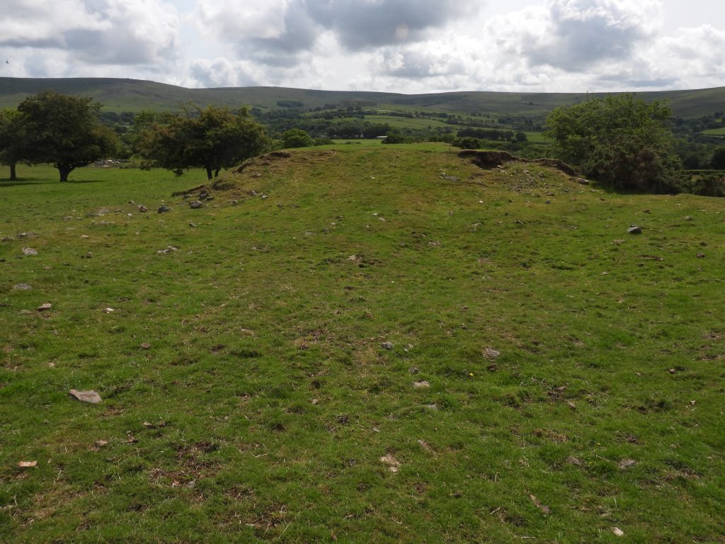
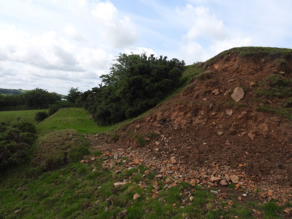
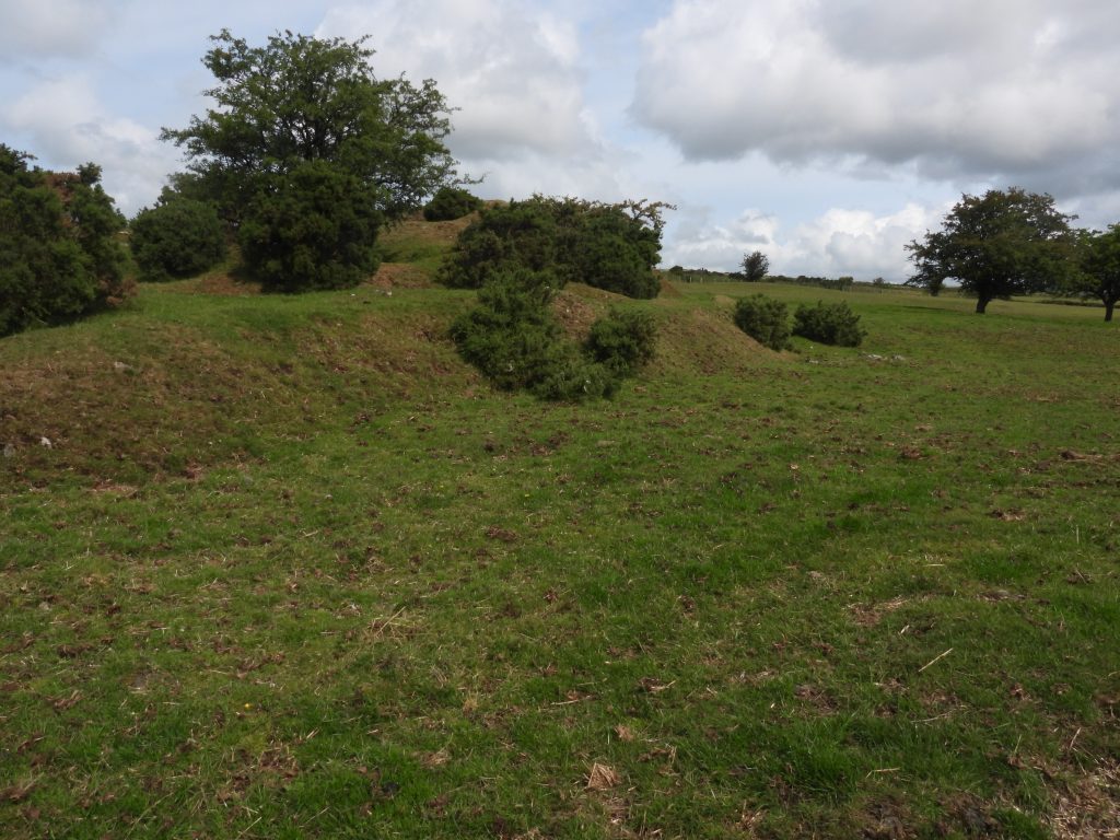
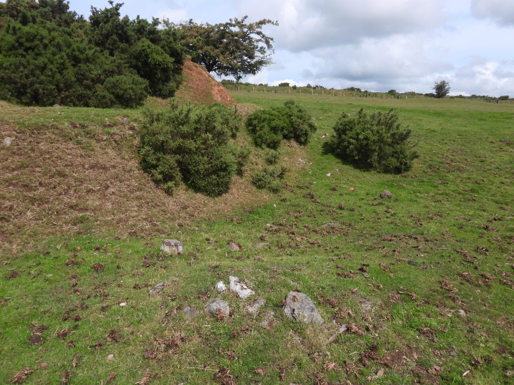
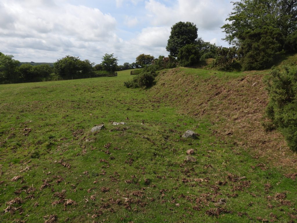
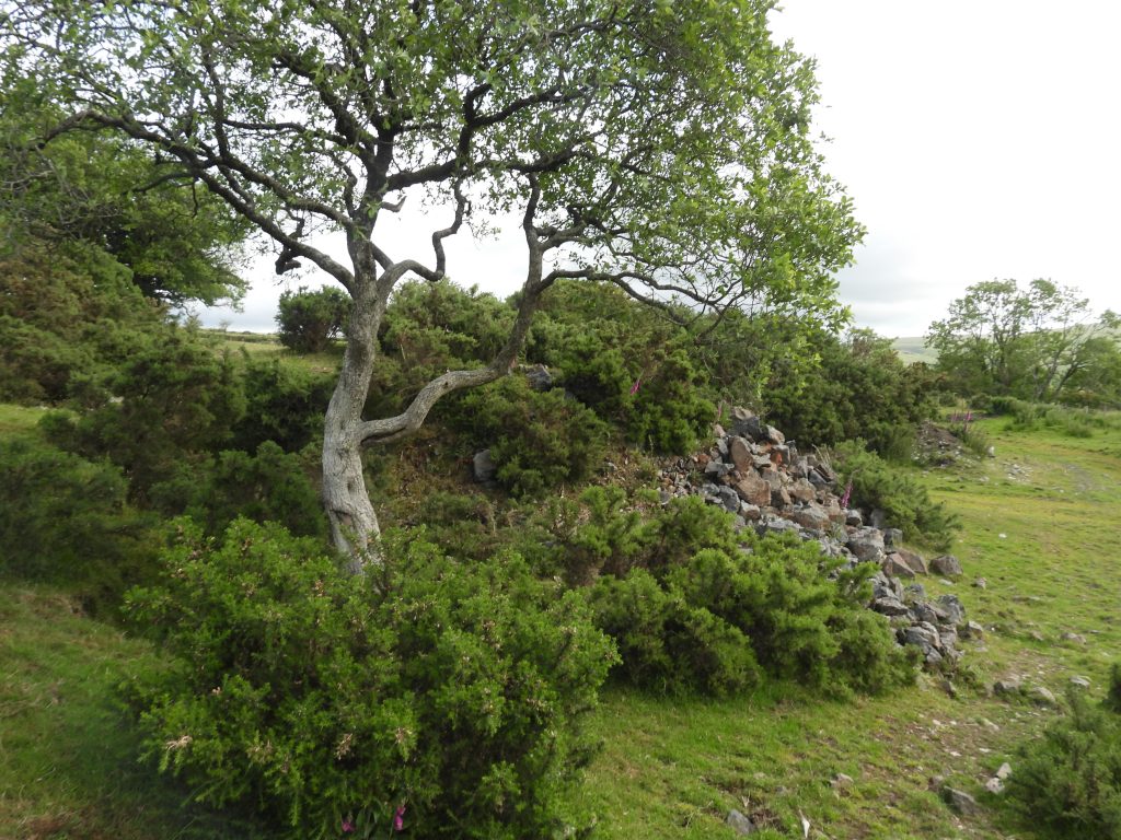
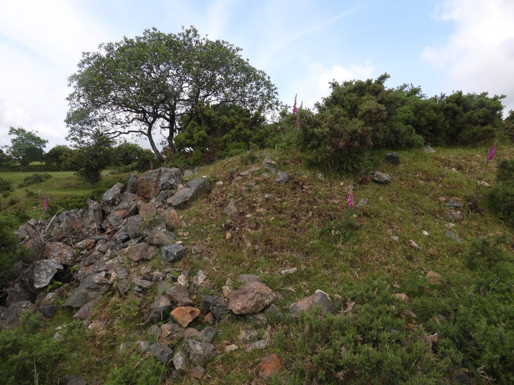
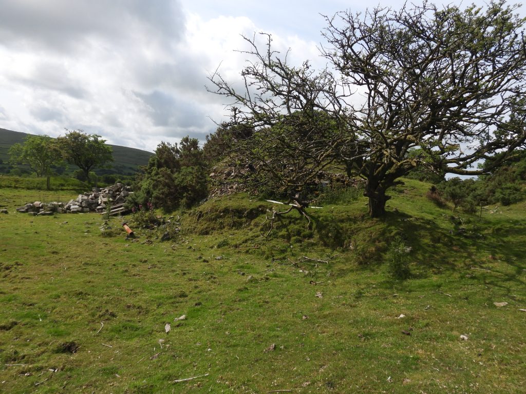
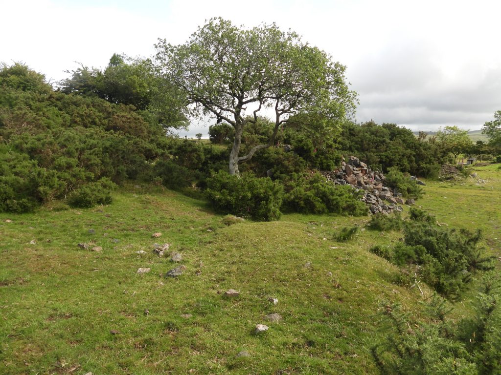
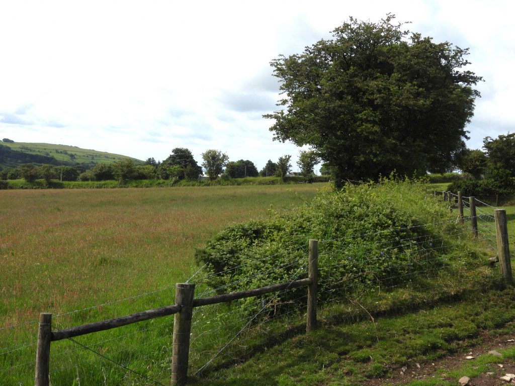
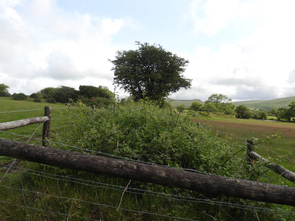
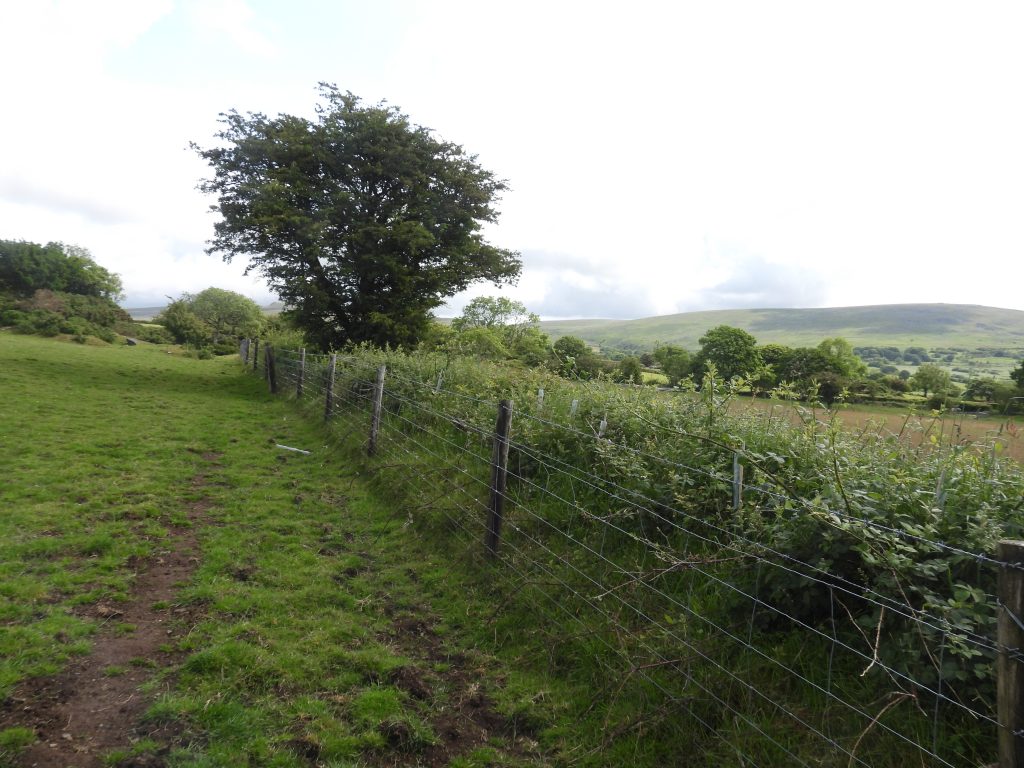
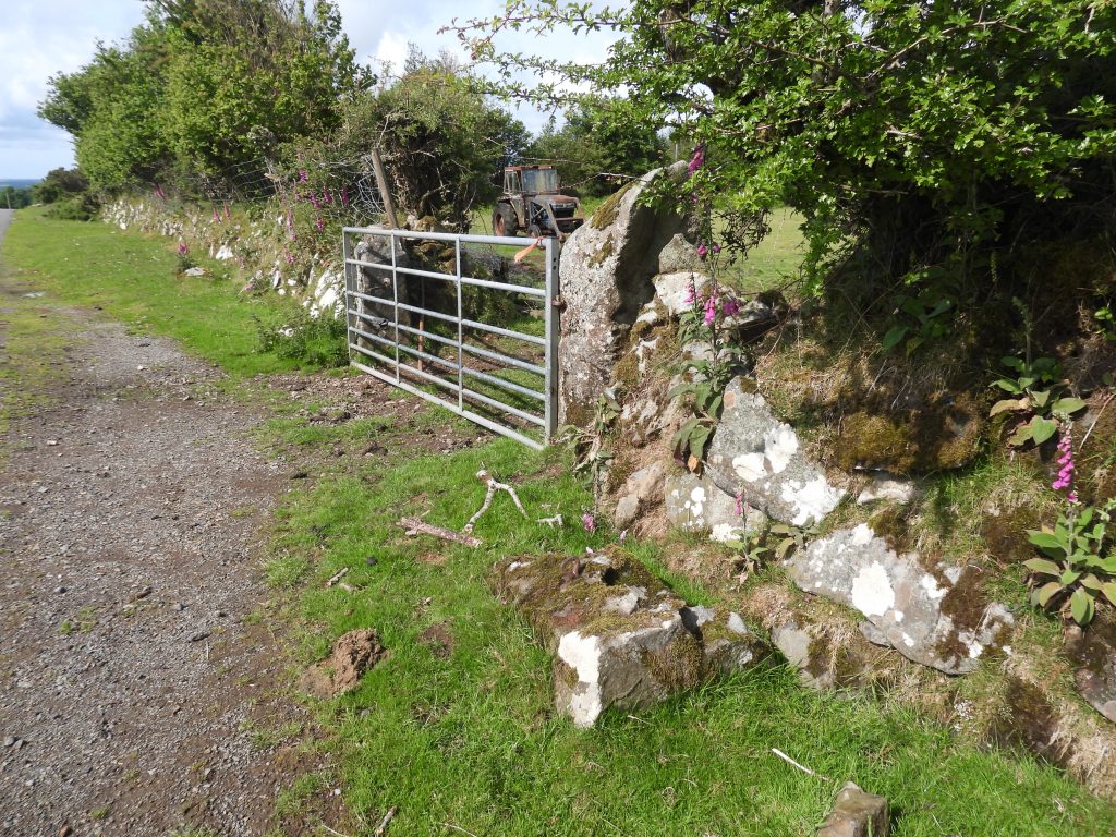
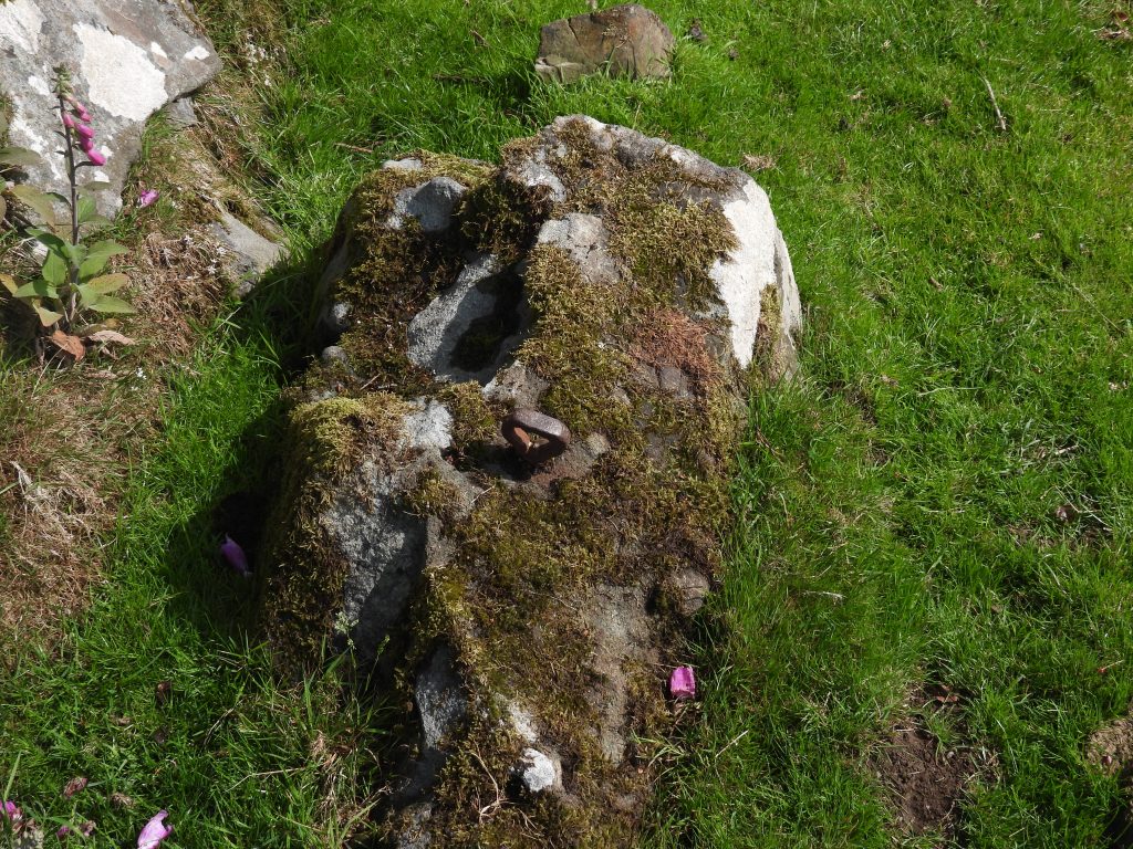
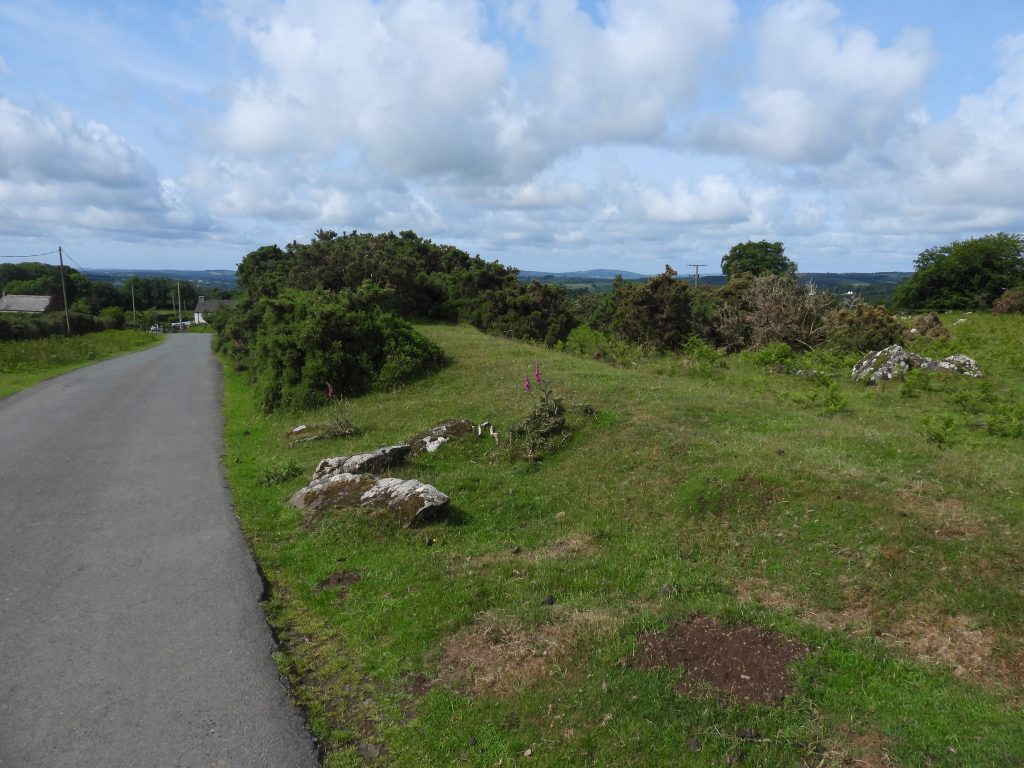
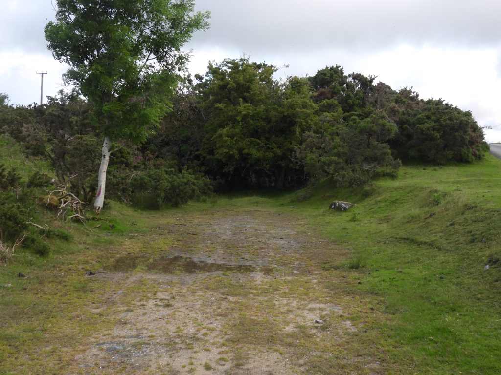
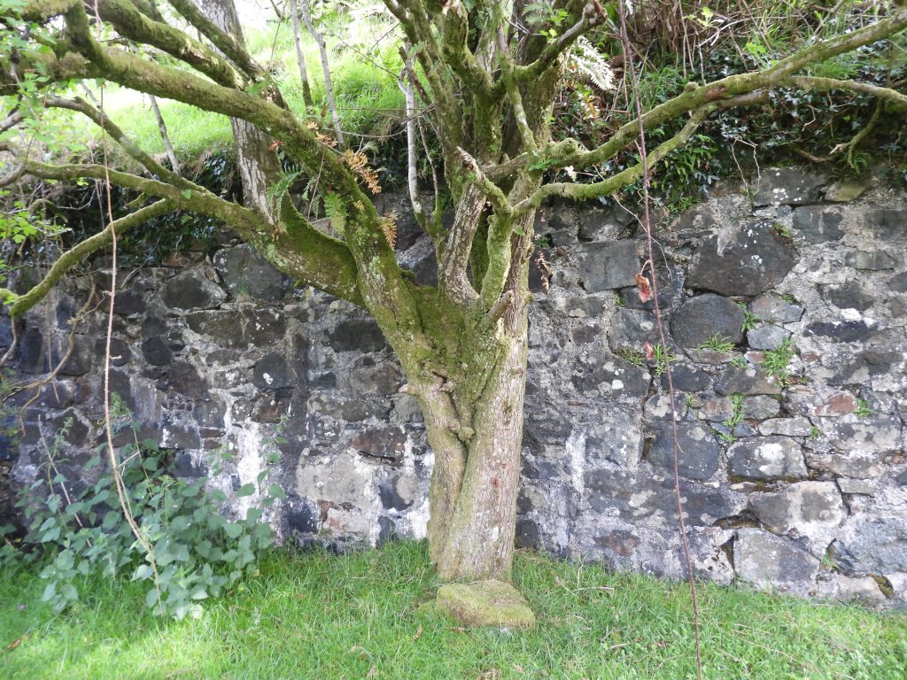
Sketch map of the Wheal Jewell operation, where much of the industrial archaeology and artefacts date for the 20th century. The ‘south area’ is on private land. This post, however, will begin around 1.5km west, where an ingenious water – air compressor system provided compressed air to the site at 90 p.s.i.This is the Richardson sketch map of the compressed air supply operation. The leat supplying the water by the extended Reddaford (Mine) Leat onto the slopes of Gibbet Hill can still be followed. The (trench) line of the 20″ pipe which went down hill (across the modern A386) to a Compressor House can still be seen on the ground and viewed on LiDAR plots. The Compressor House, next to Cholwell Brook lies just downstream from the early Wheal Betsy workings and can be accessed from the Cholwell Riding Stables concrete road. However, the 6″ cast iron main which ran from Compressor House to the mine across Kingsett Down appears to be no longer extant. According to an E.Terrell writing in 1914, the 90 p.s.i compressed air supply was used to operate pumping, winding and rock drilling machineryFrom the western edge of Kingsett Down, looking across to Gibbet Hill, the line of the extended Reddaford (Mine) Leat and the course to the 20″ pipeline which provided the power source for the Wheal Jewell compressed air system can easily be seenOn the eastern slopes of Gibbet Hill, the extended Reddaford (Mine) Leat doesn’t flow with water anymore but does flood in certain places after rain. This view if from a small bridge just above the A386, looking northFootbridge over the leat looking south. The footbridge is located at SX50800 81417This annotated aerial photograph (circa 1946-9) shows the location of the Headbox’ on the previously mentioned leat, and the course of the 20″ pipe leading down to the Compressor House near Cholwell Brook. The course of the airline is also possible to pick out from the photographThe point where Mine Leat takes near 90 deg turn at the Headbox, where masonry still remains The Headbox appears to have one leat input then three outlets, namely; the leat, the 20″ pipeline for the compressor and an excess water run off – these features can all be seen from the 1940s aerial photographHeadbox brickwork and features, which appears to have some iron work attached to it – possible for a gate and a filter. The Headbox is located at SX50646 81060Close up of some of the ironwork at the HeadboxThe obvious lead offs for the 20″ pipeline (left) and the excess water run off (right)Richardson records that he saw the Compressor in 1933. By using aerial photography from 1946-9, the location can be estimated. At the ‘inlet’ point of the leat to the Headbox, there appears to be a linear reservoir to help with getting a head of waterLeat inlet to Headbox which is partially masonry filledLeat near HeadboxStone walling in the leat not far from the Headbox. Is this possible a part of a holding linear reservoir to keep a head of water ?On the east side of the A386, in the Cholwell Brook valley, the line of where the 20″ pipeline ran is still very must discernible Descending to the through the old Wheal Betsy workings to the Compressor House there is a possible weir / plinth on Cholwell Brook at SX50919 80873Workings at Wheal Betsy near Cholwell Brook, dating from 1830’s lie just above where the Compressor House is locatedMore of Wheal Betsy workingsA wintery view of the location of the Compressor House (picture courtesy of Stephen Holley)This sketch map is an interpretation (by the author and Sue Rogers) of the Compressor House where there where two Pelton* Wheels which were used to convert water power (from the 20″ iron pipe) into compressed air which was then fed to the mine via a 6″ cast iron main. Note the sketch is not to scale. *The Pelton Wheel or Pelton Turbine is an impulse-type water turbine invented by American inventor Lester Allan Pelton in the 1870s.Overlooking the Compressor House from the north. The area where the ferns are growing is where the author believes the two Pelton Wheels were located. Two wheels were used to provide more efficient operation and helped to balance the shaft on which they were attachedThe Lester Allan Pelton patent. Note the wheel is located on a frame, which the author believes may have also been the case at the Compressor House, albeit with two wheelsLooking north over a concrete plinth (located between the Pelton Wheels and Cholwell Brook). It is on this plinth where the author believes the compressor was located. The location is SX50920 80832Immediately to the north of the concrete plinth is a cutting, which is most likely where the 20″ iron pipe for supplying water came throughAt the end of the cutting, where the pipe probably would have been located. The author speculates the pipe was located / suspended over Cholwell Brook towards the waterfall shown. It is at this waterfall the possible weir / plinth previously shown in this post is located (SX50919 80873) and might have been used to provide a turning point for the pipe where it came down from the near hillside and Gibbet Hill to the west. Located into the base of the Concrete Plinth side wall, adjacent to where the Two Pelton Wheels were located, there are a series of 8 rectangular slots. It is speculated this might be where a framework was inserted to support the two wheels. The Compressor was most likely located on top of the Concrete PlinthSupport wall at the west side of the Compressor HouseAcross Cholwell Brook just upstream from the Compressor House is a tall retaining wall, which in all likelihood was built in the 19th century to protect the stream from the Wheal Betsy early spoil tipsSmall twin waterfall by a small pool on Cholwell Brook by the tall retaining wallLooking across Cholwell Brook to the Compressor House. Note the low retaining wall, within which is the water outflow point for one of the two Pelton WheelsAnother view up Cholwell Brook with the Compressor House on the left (west side). A possible question as to why go to all the effort to pipe water down a 20″ pipe to this location where there is water already available. The author has two possible explanations: Firstly, for Pelton Wheels to operate well they need a high head of water, hence the approx 80m drop down from the side of Gibbet Hill to here; Secondly, one suspects the Wheal Jewell operation were forbidden to use water from the brook, even if it could be harnessed to drive the Pelton WheelsPanorama picture (hence brook looks curved) showing the locations of the two Outflows from the two Pelton WheelsThis curved stone is located near to where there would have been a tunnel for Outflow 1 (Picture courtesy of Sue Rogers)Archway internal to the Compressor House which leads to Outflow 2. Looking back up Outflow 2 from the brook, daylight can be seen confirming this location as where water once flowedThreaded Bolt close to the Archway for Outflow 2. Its former purpose is not clear considering its current locationOnly when exiting the site of the Compressor House, did the author notice these shallow steps, which lead operatives down the slopeLeaving Cholwell Brook valley and the Wheal Betsy workings access to Kingsett Down where the airline was located and onto Wheal Jewell Mine can be made up a footpath (which is a man made incline) which is known as Maunder’s BrakeClimbing onto Kingsett Down with a zoomed in view of Wheal Betsy chimneyPossible line of the 6″ cast iron airline from the Compressor House to Wheal JewellMore possible locations where 6″ cast iron airline was located. According to the aerial photographs, it appeared to terminate at a building, which is still some distance short of the main 20th century workingsLocation of possible building at end of Airline. There is definitely a man-made feature here. Location is SX51897 81304Spoil on west side of Kingsett DownClose up of spoil, which was possibly part of New or West Wheal Jewell Shaft. The shaft was on the Middle lode 940 yds. W. of No. 3 Shaft of the mine but the extent of workings from it is not knownThis annotated 19th century map indicates the locations of two adits, an old wheelpit and a possible flat-rod channel near to the New or West Jewell ShaftAdit 1 (from the annotated map) is quite shallow and presumably linked to New of West Jewell ShaftThe run off from Adit 1Adit 1 is located at SX51998 81161Although not documented, this channel pointed out by Stephen Holley (DTRG Chairman) is a possible Flat-rod channel as it appears to lead to the east from the area of New Shaft where there is thought once to have been a wheelpitThis is a probable (now very overgrown) Wheelpit and Tailrace near New Shaft at SX51871 81345Shallow OpenworksAdit 2 as annotated on the 19th century mapRun off from Adit 2Adit 2 is located at SX51733 81313To the west of Wheal Jewell reservoir are what looks like trial pits associated with the mineNext to Wheal Jewell Reservoir are a couple of Rain GaugesThese rain gauges are located at SX52190 81397Wheal Jewell reservoir. Electricity installers (Christy brothers) bought the water rights from the Wheal Jewell and Mary Tavy Mining Company in July 1932. The West Devon Mining and Power Company built a hydro scheme at Mary Tavy in December 1932 utilising water from a leat whose take off point was Hill Bridge. By 1936, to meet the increasing demand a second scheme was introduced, which included the construction of this reservoirThe reservoir holds 16million gallons of water and is fed through a 39 inch internal diameter ductile iron pipe to the hydro plant and its turbines from its southern end. The water source is from the Tavy in Tavy Cleave, running 4.5 miles along the 200-year-old Reddaford leat. The author has learnt that the width of the reservoir was limited by the reach of derrick cranes used from each size and the reason for the ‘S’ shape was to increase volume and to slow water down when it flowed north to southIn 1936, Mary Tavy had the largest hydroelectric power station in England. Output was first connected to the national grid in 1942.The intake from Reddaford LeatA Canada Goose on the reservoirScreening House at the southern end of the reservoirPony running in front of the Screening HouseTo the east of the reservoir, there are the remains of two buildings. The one shown in the photograph is annotated as Power House on the sketch map. The author has learnt that this building was constructed and used when the reservoir was constructed. The building is approx. 5m x 5m (but hasn’t been measured). Therefore it dates from the 20th century (it is not shown on 19th century maps). It is surrounded by a large semi-circular bank, now covered in gorseThe Powder House is located at SX52373 81417The outline of a second building (annotated as Unknown Building) is much larger than the Powder House. Maps from the late 19th century indicate it may have had an entrance (porch) located on its south east corner. In all likelihood, this construction would have been woodenThe outline of the Unknown Building is located at SX52404 81388To the south east of the two buildings and east of the screening house of the reservoir are three shafts which are located adjacent to (north of) a drystone wall. The first shaft has a section of walling in front of it and a patch of concrete with at least 10 small bolts contained in it. Dines records that No. 1 (shaft) is 290 yds. (or 265m) W. of No. 3 (shaft); which places it at this location, thus the author has annotated the map as such. NOTE: No. 3 Shaft is marked in the Richardson publication (Figure 6 on page 48) but No. 1 Shaft is notThe bolts in the concrete patch, which are just visible in the photograph, would have been used to bolt down some equipment. The author speculates that a winch may have been located here, although it is doubtful that the winch would have been driven by compressed air (from the Cholwell Brook Compressor House) as the shaft appears to date from the 19th century (as its on maps of that period marked as ‘Old Shaft’) and is not mentioned as being operational in the 20th century. Dines records that although little is known concerning this shaft it is thought that it was of comparatively shallow depth.The No. 1 shaft (with the walling) is located at SX52434 81334. The shaft lies on the Middle Lode which was said to be 2 to 20 ft. wide and mainly of quartz and chlorite with cassiterite and mispickel. There is much detritus here which appears to be both mining related and possibly from dumpingTo the east of the shaft with the walling (No. 1 Shaft) is another shaft (simply labelled with another as ‘Shafts’ on the sketch map in this post)This second shaft is located at SX52552 81332. It may well have been just an air shaft or a trial shaftClose and east of the second shaft is a third, which the author suggests may also have been an air shaft or a trial shaftThis third shaft is located at SX52570 81339To the east of No. 1 Shaft is a track which is edged by a small leat, which appears to have been fed by a small watercourse on the east side of the mineTramway from the South Area to the North ShaftThis sketch is of the North Shaft Area of the mine (on public access land) and is a replica of Fig 6, page 48 from the Richardson publication. The North Shaft was one of three shafts known to have been operational from 1912-18 (together with No. 3 Shaft and No. 4 Shaft). These features are shown on 20th century but not 19th century mapsApproaching North Shaft lies approx. 200 yds. N.N.W. of No. 3 Shaft and was sunk on the underlie to 37 fathoms below surface.North Shaft lies on the North Lode. The ore is worked here was to a width of 6 or 7 ft. on a chloritic lode, similar to Middle Lode. There were more pyritic and more sporadic tin than Middle lode. A bulk sample yielded 20 lb. of black tin per ton. North Shaft is located at SX52629 81502. Richardson recorded that there was no headgear here as it was an incline shaft, which when visited was flooded to within about 30 feet of surface. Next to North Shaft is a flat area, recorded as being the location of a ‘Picking Shed’. The location is SX52630 81495There were three buildings associated with North Shaft, namely; a Picking Shed, a Dry and an Engine ShedThe ‘Dry’ is located at SX52640 81487Edge of the Engine House foundations – concrete is still here under the turfView of the ‘Dry’ foundations looking east towards White Tor and Lynch TorThe Engine House foundations are located at SX52626 81500View looking towards Tavy Cleave. The ‘Dry’ is a rectangular shape and the ‘Engine House’ is L shaped. This sketch is of the south area of the mine (on private land) and is a replica of Fig 6, page 48 from the Richardson publication. No. 3 Shaft was the only shaft in this area known to have been operational to any extent between 1912 and 1918, although some development occurred around No. 4 Shaft (to only 6 fathoms). No. 3 Shaft extended to 70 fathoms below surface. Dines records that No. 4 Shaft is 100 yds. E. of No. 3 (and which connects with No. 3) with No. 2 Shaft being 50 yds. W. Looking over a drystone wall into the south area of the mine. Hopefully the author will be able to gain access one day and record the shafts and building remains here. Ore from No. 3 Shaft and No. 4 Shaft went into an Ore Bin situated near No. 3 Shaft. From the bin, ore was transported to Wheal Friendship for treatment. It is possible that the ore was transported using a road trailer hauled by a small steam traction engine (a rusting wreck of a traction engine is known to have been found at Brenton’s Stack at Wheal Friendship in 1935). No. 3 Shaft had steel headgear and No. 4 Shaft had primitive wooden tripod prospecting headgear (ref: Richardson)Looking across the south area of the mine to Cudliptown Down and White TorIn order to access the Wheal Jewell southern area, the author gained permission from the land owner to visit. The above picture is of a track leading from the Horndon – Willsworthy road towards the mine workingsNext to the track and in an adjacent field are the remains of a shaft marked as ‘old shaft’ by Richardson on his original sketch. There is very little upthrust of earth suggesting perhaps a shallow shaft. It would almost certainly date from the 19th centuryThis substantial earth bank can be found at the southern end of the (south) workings Top of the earth bank. It is not clear why this earth bank is here but looks like it may have been as a result of substantial levelling, which might be farming and not mining relatedProbable location of shaft 4 which is located next to substantial upthrust. Richardson (page 48 in Mines of Dartmoor and Tamar Valley), states that at shaft 4 there was primitive tripod prospecting gear, circa 1933. The location has been ascertained by the Richardson sketch on the same page in his book as quoted above. Probable location of the Engine House as identified from sketch (Richardson – page 48 in Mines of Dartmoor and Tamar Valley)Some concrete with embedded bolts at the assumed Engine HouseView looking west from Engine House. Location SX52695 81302View looking north from the Engine House. The major earth upthrust is from Shaft 2. In front of which were three buildings: Fitting Shop, Store and Office. A shallow depression (dark patch of nettles) lies between the Engine House and the upthrustAnnotated picture showing (probable) locations as viewed from the Engine House. The author had problems locating Shaft 3, since there was no associated earth upthrust nearby. That said, the area has been known to have been significantly levelled over the years. The small depression is adjacent to the Engine House so may fit the interpretation. Richardson stated in his book that in 1933, there was a fairly modern steel headgear hereNear the Engine House, amongst some trees lies a flattened area which may well have been where the Boiler House was locatedPossible Boiler House location under the trees. Some evidence of walling on a flattened area. Location SX52703 81321This small depression is adjacent to the Engine House and quite possibly be Shaft 3. However, there is no significant earth upthrust here, so that interpretation must be questionableThis depression (Shaft 3?) is located at SX52684 81306Upthrust and filled in Shaft 2. Location SX52640 81321Southern side of the upthrust taken from Shaft 2. Note the flattened area which is immediately above where there were three buildings; Fitting Shop, Store and OfficeLocation of three buildings; Fitting Shop, Store and OfficeSome evidence of the building at north end of three – The Fitting ShopMore building evidence of the three buildings; Fitting Shop, Store and Office. Location SX52665 81307The ore bin was most likely located here between the tree and the rock spoil. This is at SX52720 81294The location of the ore bin is behind this rock spoil.Earth banking by the ore bin, as indicated by Richardson in his sketchesThis is the authors speculated route of the tramway for the ore, enroute to Wheal Friendship for processingThe ore bin and the start of the tramwayThe tramway appears to run a line to this very wide hedgerow. There is no evidence here that that the tramway entered one of the fields either side of this. Is it possible the tramway became elevated here between two fields ?Is this the line of the tramway ?Probable line of the tramway. The hedge here seems extremely wide and could have possible been where the tramway had been elevatedNext to the tramway by a gate there is a metal eyelet fixed into a granite blockAn interesting piece of iron work next to the tramway. The eyelet is triangular. This might have been a tethering point or possibly a gatepost. It is located at SX52278 80467 around 50 metres from the loading bayAs the road descends the tramway becomes slightly elevated by comparison as it terminates at a loading bayThe loading bay for the ore from Wheal Jewell is now quite overgrown. It is believed that ore was transported from here via carts to Mary Tavy (Wheal Friendship) for processing. The road up to this point in the tramway has been fairly flat and takes a significant downhill to Zoar Chapel and onwards to Horndon, which may have been part of the decision to locate the loading bay hereThe loading bay wall, which is located at SX52225 80378
Not covered in this post is South Lode, which was around 150 yds. S. of the workings on Middle Lode. It was only tried by surface pitting which proved it to be from 2 to 20 ft. wide and to contain considerable amounts of mispickel in places. A 5-ton sample from a 30-ft. pit showed a recovery value of 10 lb. of black tin per ton (ref: Dines). Two other lodes are said to have been nearby; Hilltown Lode, about 600 yds. S. of Middle Lode and Lowertown Lode, about 200 yds. farther south, but neither were developed.